While most people are satisfied with a calculator application on their smartphone these days, there’s still something to be said for the old fashioned desk calculator. Maybe it’s the fact the batteries last long enough that you can’t remember the last time you changed them, or the feel of physical buttons under your fingers. It could even be the fact that it keeps your expensive smartphone from needing to sit out on the workbench. Whatever the reason, it’s not uncommon to see a real-life calculator (or two) wherever solder smoke tends to congregate.
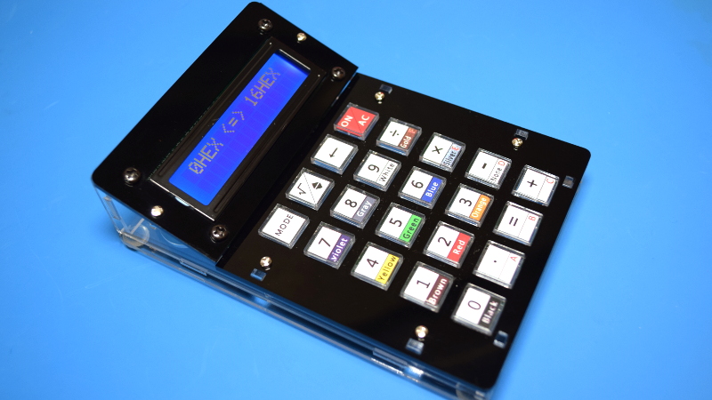
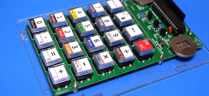
Which is precisely the idea behind this DIY calculator kit. Available from the usual overseas retailers for about $15 USD, it has some hobbyist-oriented features such as the ability to decode resistor color bands, convert hexadecimal numbers, and calculate resistor values for driving LEDs. If you’re going to keep a knock-around calculator on your bench, why not build the thing yourself?
Given the dual nature of this product, a DIY electronics kit and a functional desk calculator for electronic hobbyists, it seems only appropriate to review both aspects of it individually. Which is good, since there may be more to this product than just the sum of its parts.
Kit Review
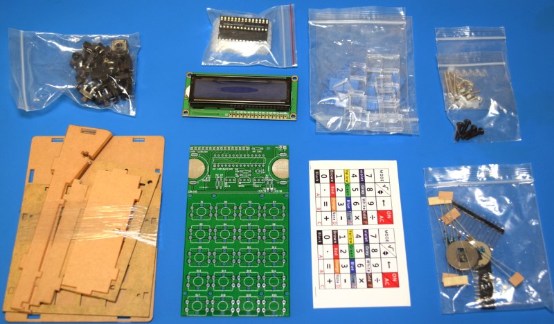
From a hardware standpoint, I was very impressed with this kit. All of the components are separated logically in their own individual bags, and there are even a few spares provided for the resistors, screws, nuts, and standoffs. There are however no spares for the buttons, nor the plastic caps that go over them. This was a bit surprising, as both components are pretty likely to have some damage from transit; several of the buttons in my kit had mangled legs, and at least one of the clear caps had a chunk taken out of it.
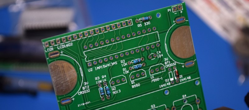
The PCB especially struck me as being of unusually high quality. Anyone who’s imported electronic components from China has likely run into thin and brittle PCBs that you can snap with your fingers, but that’s not the case here. The PCB is substantial, and will have no trouble surviving the physical stress that pushing the buttons will put on it.
In terms of documentation, the kit only comes with a printed circuit diagram and a brief overview of how to operate the calculator’s modes once it’s been assembled. There is however a QR code that takes you to a step-by-step pictorial guide for assembling the calculator. While the average Hackaday reader might not need them, it’s worth mentioning that there are no written assembly instructions that I could find.
Even if you didn’t have the circuit diagram to help you, the silkscreen on the PCB is really quite excellent. It shows the values for all the resistors, part numbers, and the proper orientation for the components that need it. If there’s any pitfall for new players, it will probably be with the installation of the semiconductor devices; there are two different types of transistors and a voltage regulator, all of which are nearly identical externally beyond their part numbers. If you’ve assembled your calculator and it doesn’t work, those are the parts you’ll probably want to double check.
There are, of course, a few sour spots. The laser-cut acrylic enclosure, while it looks very nice when assembled, doesn’t go together very well. The small pockets cut into the plastic to hold the nuts are too large, and I dropped them into the case during assembly more times than I’d like to admit.
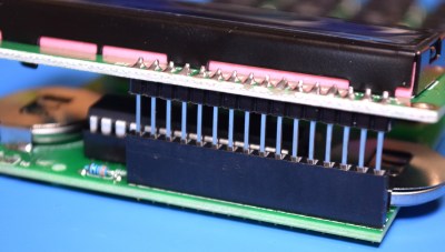 The interconnection between the main PCB and the LCD module also leaves something to be desired. Rather than wires, the kit has you connect the two components with long pin headers.
This would be fine if the boards were to be installed parallel, but to fit inside the enclosure, the LCD needs to be at an angle. Bending the pins is a fiddly operation, and took a few attempts to get right. Not a huge deal, but it does seem like an oversight considering how well the rest of the kit went together.
Calculator Review
While the hardware was a pleasant surprise considering how cheap the kit was, the software is another matter entirely. For one thing, there are annoying glitches throughout. Such as characters disappearing from the display, or the fact that only some buttons seem to be registered by the calculator’s inactivity timer. Several times the device has turned off while I was using it, apparently because I had been shuffling through modes instead of entering numbers.
While it might not be a problem in day-to-day usage, one of the biggest surprises to me was that I could only enter in 7 digits. This seems an arbitrary limitation on a 16×2 display, especially when the answers can be longer.

Although, not much longer apparently. If you try to calculate too large of a number, it will quite literally tell you that it can’t do it. We’re not even talking scientific notation stuff here, even numbers in the tens of millions are beyond this device.

On the subject of the firmware, I was also disappointed to find that there doesn’t appear to be a public release of either the code or binary that the calculator’s STC IAP15W413AS microcontroller is running. On a DIY kit with a socketed MCU, you’d think there would be at least some provision for updating or modifying the firmware. Though to be fair, nothing it the kit’s documentation or marketing lead me to believe this would be the case.
Beyond the firmware and usability issues, the enclosure of the calculator is designed in such a way that changing the batteries would require the entire kit be disassembled. Seriously, you’d have to take the whole case apart and remove the PCB from it just to pull the two coin cells out. Perhaps that’s the reason for the calculator’s incredibly aggressive automatic power off feature.
Hacking Possibilities
While the out-of-the-box experience might not be too hot, we don’t worry too much about such things here at Hackaday. There’s at least one open source project that offers a Reverse Polish Notation (RPN) replacement firmware for this calculator, capable of handling up to 18 digits. This firmware doesn’t include the resistor calculator and hex conversion functions of the original, but anyone looking to turn this kit into a proper tool for mathematics probably won’t mind the trade.
The project goes to great length to document the calculator’s hardware, going as far as to identify compatible components that can be used as drop-in replacements or upgrades. For example, you can replace the original blue-lit LCD with a transflective type that is a bit easier on the eyes. To make the transformation complete, it even includes new cutouts for the calculator’s keys.
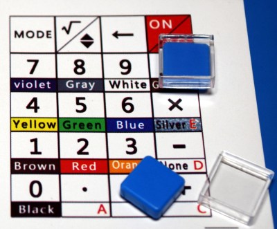
It’s those new key inserts that actually has me the most excited about the possibilities for this calculator kit. Being able to create your own artwork for the buttons allows you to completely customize the device for whatever functions you could need.
That might not be terribly useful if you stick with the STC IAP15W413AS, but what if you ripped that out and replaced it with an ESP8266? With the included wiring diagrams, connecting the key matrix up to the more powerful MCU and the HD44780-compatible LCD would be simple enough.
Now you’ve got the makings of something really special. Perhaps a handheld MQTT home automation controller with custom button art that represents the devices you want to control, or maybe a little macro pad with its own display, perfect for controlling Kerbal Space Program. For the price, it’s a very compelling platform for further hacking that will hopefully start getting more attention.



Now I kinda want to get one of these and try to interface it to KSP…
At that point though, I would rather it be cabled than have to change batteries. :/
Hmmm…I find it easier to pop-up the calculator of my choice on the PC. No extra desktop space required, no batteries, no terrible display, no funkiness , no assembly required, and free.
Do you guys happen to know the name of those buttons with key inserts? I’d love to add some to my projects!
I think they are Tactile Tact Switches. They just have a clear cap over the button.
https://www.aliexpress.com/item/32381083884.html
https://www.aliexpress.com/item/1964323004.html
They are generally called ‘relegendable’ keycaps.
The 7 digit limitation would have me seething in this day and age when a decent scientific calculator can be purchased for similar money to this kit. Of course, a new MCU with custom programming would fix that, but that seems a bit much for what you end up with.
In some ways, I want one of these now. It looks nice and it certainly has nerd appeal. The housing and keys look good.
On the other hand, the coin cells in combination with the LCD seems like a really bad idea. That thing isn’t meant to fit in a pocket anyway. So why not use standard AAAs? And if only it would contain an Arduino Mini or a Blue Pill as CPU. I would definitely order a few…
If it has a Blue Pill, why not a 3.5″ display and graphing? Ah, I can feel the feature creep! It needs Postfix. Soon it will be this (which would be pretty cool) https://www.swissmicros.com/dm42.php
There is also this :
https://www.numworks.com/
with open-source firmware for its STM32.
I bought one – it seemed a useful thing for the bench – but was concerned about battery life too. I need not have worried. Two years of intermittent use later, it’s still on the first set of batteries. But the keys are a pain. No amount of finessing could get them from sticking. Resorted to filing holes and messing about for an hour or two before it came right.
Like many projects featured on HaD, this one may be more useful for inspiration than as something to buy or replicate. By using an AVR or maybe an STM processor, this might be a nice form factor for a general purpose controller. By making a batch of the boards and case parts, and leaving a bunch of area for deadbugging, this might be a nice platform that can be slpped together in an afternoon. I like things like this better than trying to control things with a smartphone. I don’t like everything to be wireless and sharing the same physical interface.
Some other ideas:
1) Use stack-of-PCBs instead of laser cut acrylic.
2) Use a display that doesn’t need a backlight.
3) Add amorphous silicon solar cells to charge either a capacitor or a Li-po.
A few years ago I bought one of these kits.
My findings are pretty much the same as this review.
It’s quite a nice hardware kit, the housing is a bit finicky to put together because of the loose nuts (It helps to glue them in place with transparent glue) and the software in this thing is horrible. Just simply unusable.
I had no trouble with the LCD header. Just put the header in the PCB and then lay the header flat on the table (LCD PCB vertical) and then rotate the PCB while pushing it to the table. Or bend the ends of the pins one by one with pliers to the correct angle (same angle as in the perspex)
The buttons are real nice, and that was the main reason for buying it.
I never ran it from batteries, Instead I drilled an extra hole in the housing and added a 5.5/2.1mm plug and connected it to the pads in the right top of the PCB.
For the buttons alone. A search like below will get you quite close:
https://www.startpage.com/row/search?q=aliexpress+pusbutton+cap+transparent+square
Can you re-program it? Do you have to remove the MCU from the board to do this?
Did you try reading the article?
… in the hardware section of https://github.com/jjj11x/stc_rpncalc
Thanks
Did you try reading my question?
From the article – “you’d think there would be at least some provision for updating or modifying the firmware. Though to be fair, nothing it the kit’s documentation or marketing lead me to believe this would be the case.”
The article does not reach a definitive answer on this question.
I downloaded the data sheet and the schematic.
The MCU is a single cycle per instruction equivalent of an 8051 that can run up to about 35MHz.
So it’s a good entry point for someone who wants to start ASM. It’s a simple 8-bitter with relatively few configuration parameters (and hence registers).
The schematic shows that the programming TX pin is used for the keyboard matrix. The RX pin is used to detect power off and has a diode to the voltage control and this may interfere with programming.
There is no onboard USB/Serial interface but who here doesn’t have half a dozen or more of these in their junk box.
Additionally the chip uses an internal oscillator that may not be so frequency specific and may cause baud rate problems when programming.
So I though it best to ask someone with some experience with this board as the documentation is limited.
So in summary, I have researched before asking this question and you don’t appear to have done any research before shooting off your one line dismissal of my question.
Pretty long way of saying “No, I didn’t read it”
The last section talks about a replacement firmware, all you had to do was click the link during your “research”.
@[Reading Rainbow] or [TLDR] who I suspect is BrightBlueJim.
I note that your comment is completely devoid of any technical information.
Where do you get off telling people what they can and can’t ask or what comments they make here.
Your not a moderator here, thank god!
I really don’t give a damn for your comments, they contain no useful information whatsoever. They’re simply gas flaming from someone who has not demonstrated any technical ability whatsoever.
Thankfully [ergomacros] provided the link I missed. Would you now like not to scorn this person for responding in a positive manner.
So here’s the TL;DR for you. If you can’t offer some positive or usfull comment then perhaps it’s better if you don’t comment at all.
If you keep being so negative here you will get lots of flack. Get used to it.
Eventually you may work it out, but I doubt it.
You don’t need to write in assembly. There are C compilers for the 8051. SDCC is available but the code quality isn’t that great last time I looked at it.
As for the Rx and Tx pins, you just have to leave the switches alone during programming. Analyze the circuit and you’ll find out that programming isn’t affected. You can pull the chip out too.
There are custom mechanical keyboards with more processing power than this: several keyboard designs use a Teensy, for example. I’ve often wondered how hard it would be, to add an LCD and have a calculator in your keyboard.
Of course, you would need to find a way to add the labels of secondary functions to keycaps. Using waterslide decals on the front face of keycaps only works if you have white / light plastic…
ugly screen , trouble with show greek, polish or mathematic symbol
I prefer simple AA battery and solar panel. Why this calculator not programovable? similar old hp or similar basic in zx spectrum. Macintosh have 8Mhz processor and better graphics
this is an 8-bit character LCD and you compare it with Mac graphics? :-)) how old are u? your name seems a young dude.
I bought this calculator kit just for the casing and some other parts, and will design my own PCB for it. First I need to measure the board carefully, in order to get the buttons, screw holes and display connector placed in exactly right positions. I will use an ATmega32A instead of the original chip, and will write my own program (which will be the real challenge in this project).
The display needs to be replaced by a version which is readable without using the backlight, to reduce power consumption. CR2032 cells won’t last long if you draw any more than few milliamps from them. It’s a pity there’s no room for any better ones in this casing.
You should be able to put small battery behind the LCD. A small LiPo with a charger + boost converter should work.
Those LCD blacklight can work down to 1mA and still viewable indoors.
Hard pass.
This is a great executed idea! I wish I’d made it :-)
The keyboard with the transparent key caps is the most interesting thing of this kit, and as I should have guessed before, you can buy such keyboards directly from Ali for a very low price.
For example:
https://nl.aliexpress.com/item/32635207928.html
Free42 : An HP-42S Calculator Simulator
https://thomasokken.com/free42/
Above comment was supposed to be a reply to the post by @Occam: July 3, 2020 at 10:53 am. But as usual the horribly broken comment engine that HaD runs now mangled my reply and relegated it to the bottom of the thread. Oh well, I’ll just be thankful my reply appeared at all. Sigh…
It sounds like the default firmware is using single precision floating point library for the math, which would explain why it starts to kick out stupidity above 2^24. Thing is even though it is much more time consuming to do double precision on an embedded micro, at human scale you wouldn’t notice it. The Saturn processor behind the most successful HP calculators was breathtakingly stupid by modern standards but we all loved it at the time.
I have one of those kit on my bench right now but haven’t started on building it. It was always my intention to modify the firmware after I played with it but now that I see that the files aren’t available I’ll investigate the RPN firmware mentioned in the article.
The documentation for the replacement firmware is excellent! :-) https://github.com/jjj11x/stc_rpncalc
Hello,
Nice case and material, but bad sw in the uP. But i have made a new board with a Arduino pro mini on it.
I have developed new software with 18 functions. And the new board is also suitable for other purposes.
I have made therefor a prototype with the promini with long wires And the real new board is in production.
As it is ready i will give it free. The software is multilinguage, made with the the Arduino IDE.
Some of the functions: floating point calculator, conversion HEX,DEC,BIN,CHAR, stopwatch, item counter,
temperture measure, light measure, Xc and Xl calculation. 4R,5R resistand, IR remore receiver/ decoder,
and a dice and jumping game. All in one program.
Hi Ruud!
Did you ever get anywhere with this? I’m looking into doing something very similar…
Yes I have made it with a Arduino pro mini uP.
It will be published in the elektor magazine in a few months. It comes also available as a complete set in there store.
Thanks Ruud – I’ll keep an eye out for it. Not exactly what I hope to do, but lots in common. My project is more like the TI Programmer LCD, with added remote control. I’ve got some vintage bubble LED displays, or might have a go at 10 or 12 digit LCD with Holtek HT1621 drivers. Making a nice keyboard’s a bit of a problem, so I might re-use a ‘real’ calculator keyboard, but I’ll wait to see what you’ve done first.
Hi Mike,
The bubble leds are nice, but you can’t buy it.
The multicalculator I have made have 22 functions, one of them is reading and decoding remote controls. But also temperature measures and a stopwatch. AWG calculation. And more. These keys are nice because you can easily change the text on it. The total concept is so that it can also used for other purposes. Ik have seen the prototype they haven made. And also my first models I have made with a group of members from the Arduino trainings I deserve as Arduino teacher. Greeting from the Netherlands.
I’ve just built this device and although it ‘works’, the screen just puts out random data… key presses don’t lead to intelligible text.
The chip is in the right orientation, the transistors are correctly placed (three different types), the solder joints appear to be good and I’ve put a multimeter across the resistors and all read correct for their position bar one (which I know is correctly placed as it was one of three that were attached to the correct value label).
Any ideas – apart from buying a Casio?
Enter [8] [-] and the display reads 8-8 as if you entered the second eight. I don’t trust this thing for serious calculations.
There is another version of this calculator.
A arduino version with 22 functions.
It is developed by myself, and available by Elektor worldwide as a multicalculator set.
Look at the international site from Elektor.
https://www.elektormagazine.nl/labs/elektor-multicalculator-kit-220684#/comments/81405
Look at for the Elektor multicalculator version. Available as set worldwide by elektor.
https://www.elektormagazine.nl/labs/elektor-multicalculator-kit-220684#/comments/81405
Look also on this page to order the elektor multicalculator set.
https://www.elektor.com/products/elektor-multicalculator-kit-based-on-arduino
Dear Ruud,
Nice Kit this calculator. You commented that there is a newer version 1.2.zip. Its filename adds ‘…complete … ‘.
My Question : do I still have to add the extra 2 libraries, as mentioned in the early Elektor 1.1 construction and user manual? (Today I’ve made the kit, tomorrow I try to install ‘your’ software. I have not yet checked the contents of the zipfile)
Thanks for your attention..
In the new version V1.2 you also need the library’s, the same as for V1.1.
As you have these early installed no need to change something. It will be used automatically.
See the information in the manual and in the 1.2 zip file. And yes, the new function 4 is added, all other functions goes one up.
And there is also a unboxing video from Elektor magazine.
Look at:
https://www.tiktok.com/@elektorlabs/video/7404195541770325280
or
https://www.youtube.com/watch?v=HxdT5DiCvEM
Hello everyone. I also purchased the diyleyuan calculator and found that the leading character of the first row was missing until you pressed the clear button. I discovered that when I replaced the 16 Character by 2-Line LCD Display with a different Brand, it worked properly. I hope this helps someone else.