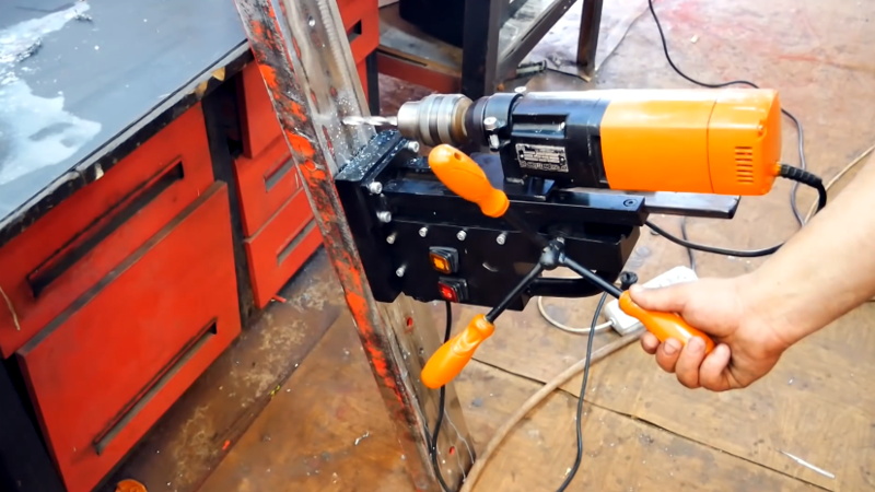
For most people, a broken tool is at the end of its useful life. But rather than toss a heavy-duty drill that had its handle broken off, [Workshop From Scratch] thought it was a perfect opportunity to create something new. In his latest video, he shows how he converted this old hand tool into a magnetic drill press with predictably impressive results.
Despite being assembled largely from pieces of scrap metal cut into shape with an angle grinder, we wouldn’t blame you for believing the end result was a commercial product. From the handles salvaged from chewed up old screwdrivers to the scratch-built rack and pinion assembly, the attention to detail here is really fantastic.
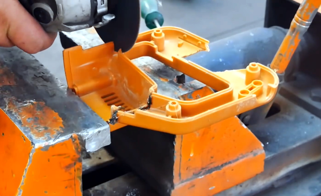
It’s difficult to pick a favorite detail, but the reinvented enclosure for the drill certainly ranks up there. [Workshop From Scratch] could have simply bolted on the tool as-is, but instead he surgically removed the vestigial handle to make it look as though the drill was always meant for this application. After cutting, it was finished off with some body filler, a bit of sanding, and a coat of his signature orange spray paint.
When he built his magnetic vise, [Workshop From Scratch] used magnets pulled from automotive air conditioning systems. They got the job done, but were somewhat annoying to work with given their round shape. This time around, he’s used off-the-shelf magnetic locks intended for steel doors. When energized with a 19 V laptop power supply, he says the three rectangular electromagnets have a combined pull of 540 kilograms.
If you don’t have a broken drill to use as a donor for this type of project, don’t worry. You could always use a salvaged hoverboard motor instead.


Wow, pretty neat. I like the use of old screwdriver handles as grips.
Some nitpicks:
(1) 12VDC switch being used for 19VDC. That mores than a 50% over-rating, but is _probably_ ok compared to the next point:
(2) Unknown current-rated DC switch being used on inductive load. This requires some notable de-rating and/or snubbing to last any reasonable amount of cycles. Otherwise the arcing will be beyond what this switch is designed to cope with.
(3) Spraypainted handles will rub off in no time, it would have been better to leave them be.
(4) Soldered crimp connectors. From what I understand this increases the chances of failure (over just crimped connections).
Fun distraction: my 1897 copy of the American NEC recommends/requires crimpable connections also be soldered :D https://archive.org/details/00701897
(5) car putty on the plastic body will crack due to thermal or mechanical stress without some internal backing (like some fiber+epoxy)
Otherwise nice build without mill nor lathe!
“Soldered crimp connectors. From what I understand this increases the chances of failure (over just crimped connections).”
It actually increases the chance of failure over both crimped *and* soldered connections (on a connector designed for solder or just cutting the connector and soldering the connections directly). It’s a “worst of all possible worlds” situation.
First, the joint formed in a proper crimp is a compression weld. If it’s done right, it won’t come apart before the connector itself comes apart, because the wire and the connector are essentially one metal object. When you solder it, the connection between the wire and the connector is now a soldered connection, which is *worse* than the original welded connection.
Second, the solder increases the rigidity of the connector. This is why you can get fooled a bit if you crimp & solder a connection and the pull strength seems larger: you may have increased the strength of the connector, at the expense of the reliability of the joint between the wire and the connector. And in doing so you move the stress of the connector all to the point where the solder stopped – the crimp flexes for a reason. Pull strength’s only one measure of a joint.
Third, there’s a good chance some solder will flow into where the connector mates, meaning that the mating geometry’s wrong now. On some connectors this won’t matter much, on others it’ll be a big deal.
That being said, if your crimper sucks (or it’s the wrong one!) and you don’t really have a choice on the connector, flowing solder into the connection and then adding more strain relief is probably better than a bad crimp. And the way to test if you’ve got a crap crimper is to test it to destruction after you do it, so if it’s a one-off… meh. Know what you’re doing.
Yes, a properly crimped connection shouldn’t be soldered.
Crimping makes a so called “gass free” connection, or one could say, “squeezed sufficiently to practically cold weld itself.”
And one can actually look at a crimp and determine if it is good or not. But you will need some micrometers and a microscope. (or one can actually look at it by eye, its just a lot less comfortable…)
Its also a very efficient way to look for wear in the crimp tools themselves.
Here is a handy document about proper crimping: https://www.te.com/commerce/DocumentDelivery/DDEController?Action=showdoc&DocId=Data+Sheet%7F1-1773838-7%7F0718%7Fpdf%7FEnglish%7FENG_DS_1-1773838-7_0718.pdf
(Also have to say that TE connectivity has some very ugly looking links for their various documents…)
Actual on the crimping + soldering note: that might only apply if you are using proper crimping tools + pressure. Not sure.
*sigh* Hackaday only inlines replies if you have Javascript enabled. Otherwise it takes you to the comment field (as if things are working fine) but your comment ends up elsewhere. >:(
Looks great, just add a safety chain for any overhead or horizontal work.
Who cares about safety features when you get that sweet youtube view$$$.
He’s only got 56k subs, I doubt he’s making much on YouTube unless he’s on Patreon or something similar.
very creative repurpose. Like this idea a lot. Great work.
On the crimp connections: What’s bad is tinning the wires, and then crimp on the connector – because tin is not elastic, so it will not form a good permanent connection, Crimping on the connector and then soldering the wires TO the connector is fine.
On 19V on a 12V switch: This won’t make a difference, there is no significant difference in isolation requirements between 12V and 19V, what matters more is the actual current being switched.
In my own experience, soldering after crimping is equally bad, or perhaps even worse as the failure will happen sometime down the road, and it usually becomes a high resistance point (read: electric fire starter) shortly before failing completely. The reason? The copper strands flex at the edge of the solder with vibration, eventually breaking. When left unsoldered, the strands can move around a bit, preventing this type of failure.
“Crimping on the connector and then soldering the wires TO the connector is fine.”
Think about what you’re doing. If you crimp it right, the wires are welded to the connector. They won’t pull out. They’ve basically got as much mechanical strength as you possibly could have between the wire and the connector.
Now you go ahead and heat it, and flow solder into it, and you’ve just made that joint *weaker* – the metal at the joints partly dissolves into the tin, and the wire-tin-connector bond is weaker than the compression weld. Plus the solder won’t even much flow into that joint, it’ll mostly flow into gaps upstream of the wire. So now you’ve stiffened the connector – it can’t flex as much.
And if the connector’s not crap, it’s got a strain relief mechanism behind it, and you likely just stiffened the wire past that strain relief mechanism. Which means the connector now flexes less, and the strain relief mechanism behind the connector can’t do its job as well.
To be clear, if you’re a hobbyist, you don’t trust your crimper (or you’re bodging something up), and you then take pains to strain relief things elsewhere, the connection’s not going to like, pop off or something (although you might screw up the mating of the connector). But in a production environment where people designed connections and do like, finite-element stress analysis on things, it’s not ‘fine’ to solder a crimped connections.
Some thoughts for v.2….
1.) Some kind of counterbalance and spring return.
2.) Maybe a strain gauge, so you can maintain constant effort.
lol all you people whining about soldered connectors. Am I the only one constantly cringeing at the youtube metalwork hacks who leave the mill-scale on their hot-rolled and just paint over it?
No?
(pickle that s**t overnight in vinegar, it dissolves right off)