Neon lights have inspired much prose over the years, with their attractive light output receiving glowing adulation. [Pierre Muth] is a big fan, and decided to spend lockdown creating something suitably pretty for his desk.
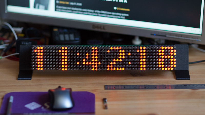
The project consists of an 8×48 matrix display constructed out of INS-1 (ИНC-1) tubes. These tiny neon tubes are 6.5 mm in diameter, showing a bright orange dot of light when powered up. Requiring just 100 V and 0.5 mA to light, they’re a touch easier to drive than the famous Nixie.
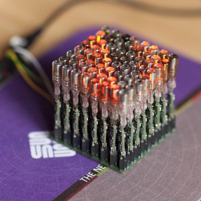
[Pierre] decided to go all out, wishing to replicate the capabilities of smart LEDs like the WS2812. These contain a microcontroller built in to each LED, so [Pierre] would have to do the same. Each of the 384 neon tubes got its own bespoke PCB, containing a PIC16F15313 microcontroller, step up voltage circuitry, and a 6-pin connector. (Whoah!) When each bulb was soldered to its PCB, they were then plugged into a backplane. An ESP32 was then employed to drive the display as a whole.
Creating a display in this fashion takes a huge amount of work, with most of it being soldering the 384 individual bulb PCBs containing 11 components each. We have a lot of respect for [Pierre]’s work ethic to get this done during lockdown, and the final result is a gloriously retro neon matrix display. We’ve featured other neon matrixes recently, too. Video after the break.


It’s bonkers to think that every pixel needed to be soldered to its own carrier board *and* the microcontroller on that carrier board then needed to be flashed. That’s a heck of a lot of pixels, and this was pulled off sooooo beautifully. Amazing work!
They should work with far lower current. Less heating, longer life.
Anyone else thinking of Lite-Brite after seeing this?
That would make an incredible Lite-Brite! Might be kinda scary to be plugging into 100 V backplane though.
Individual step up converters for each pixel! A little crazy :-)
I had expected some HV…something 64 output driver, perhaps even in multiplexed matrix configuration.
You should be able to FEEL the light turn on by the heat it gives.
If you modified the MCU code driving the step up circuitry to bring the drive voltage to just below that needed to ionise the tube’s gas, you’d have a handy 384 pixel array you could use to visualise the spatial distribution of RF, like microwave oven leakage.
I was expecting one of the high voltage Supertex chips like the HV507. Glad they still make stuff like that. Cool project though.
It’s neon, people. Use a 1:1 isolation transformer (or heck you can even step down if you want, just need to exceed the neon breakdown voltage), one diode to half wave rectify it. Use this as the common high side to all the neons, through individual current-limit resistors. On the low side of each neon, an SCR to ground. Then you only need a tiny bit of gate current into an SCR to turn on the associated neon. SCR latch-up is non issue because half wave sine supply.
Or you can try coming up with individual controllable HV DC supplies for each element. Or, ok, one HV DC supply and figure out how to switch HV DC to 10 or 40 or 384 elements, because, you know, you just like DC.
Then every 6 months, reverse the polarity of the diode to balance wear on the elements.
Wow, that is cool! Great job soldering all those Neon’s and keeping them straight! :-)