We’ll admit it, we’re all spoiled. A few bucks can now buy a computer that would have been the envy of everyone back in the late 1970s or early 1980s. So it’s no surprise that [krallja] was able to use an old-style video output chip to drive a TV with an Arduino. The TMS9918A is a venerable output device, and if the old computers could drive it then it makes sense that a modern computer could too. You can see a video of the whole experiment, below.
The Internet has also spoiled us, in that it’s dead simple to find datasheets for nearly anything, even these old chips. The only real problem with such aged silicon is that they typically expect a processor with a data and address bus, but most microcontrollers now keep all of that internal. But with enough fast I/O you can simulate a bus just fine. For now, the experiment just cycles through the color output.
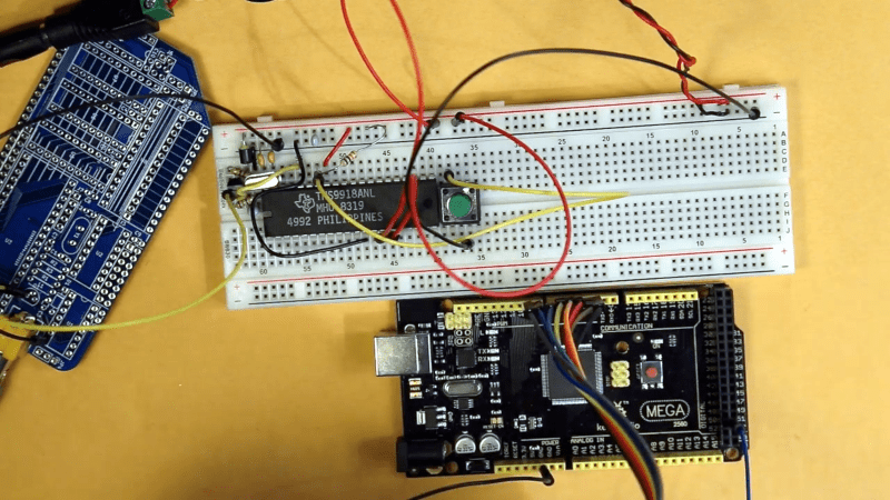
The circuit on a breadboard worked fine, even if it looked like it wouldn’t survive much transportation. The next step, which we expect will be in the next video is, of course, to write data to the video RAM so actual text will appear on the screen.
One of our favorite projects from the past did the opposite: it uses an Arduino as many devices on a Z80’s address and data bus. We’ve also seen this same TI chip used in a graphics board for the RC2014 computers.


It turns out there was a console that used the TMS99x8 with a 6502 – the CreatiVision, completely absent in North America.
It’d be interesting to directly inject video data to the TMS9918’s data bus. I wonder whether there’s enough flexibility to really extend anything.
Having finished thinking this through … Graphics 2 is already the best you can get as far as the underlying data goes (two unique colors per 8×1 region), but it looks like the sprites should be really quite extensible, with all properties (X, color, bitmap) for each of the 4 drawn sprites per scanline changeable on every scanline.
Thanks, I love both Al Williams always-on-point reports, and interfacing vintage silicon with modern and popular micro-controllers (I’m doing it myself with other ancient emblematic sound and video processors) especially when this is taking the exact counterpart to the trend of retrocomputing “purists” replacing such chips in their precious industrial artefacts :) with FPGAs providing HDMI output. And doing so, you can get the fun and acquire expertise without spending money in overpriced antiques, since you can easily find one (chinese clone) of that TMS chip for two bucks online.
Now to display something more than background color, it will need 16K of DRAM connected to it as video ram. So in order to “directly inject video data” as suggested above (effectively bypassing the bottleneck of pushing it all through the VDP) it may be possible but difficult to “emulate” this memory with an Arduino that would need to continuously “listen” and respond to the succession of adressing signals within very tight timing requirements… This would defeat the purpose of leveraging video generation to this chip, while being probably even more taxing than single-handedly generating the NTSC signal (and a wider color palette) on an Atmega with appropriate crystal clock and enough (much faster) onboard ram, like it has been done usually.
You don’t need DRAM. You can use CAS RAS and an 8 bit latch to drive a SRAM.
No ATmega has enough RAM to make this useful.
Also, you could output simple VGA if the H res is low enough.
“The only real problem with such aged silicon is that they typically expect a processor with a data and address bus, but most microcontrollers now keep all of that internal. But with enough fast I/O you can simulate a bus just fine.”
That might be true of IC’s that were designed for specific microprocessors in mind like the 6526 CIA, but the TMS9918A isn’t one of those. Signaling-wise, the TMS9918A looks like a simple 8-bit parallel latch with two strobes and a mode select. It has simple timing constraints so you don’t even need fast I/O (just enough pins to drive it) since all of the real-time stuff is handled by the TMS9918A. If needed, an I/O expander IC would work just fine.
The TMS9918A was used in the TI-99/4A computer, the Tomy Tutor, the Colecovision, most MSX-1 computers and various other lesser known microcomputers and game consoles.
It’s lack of a full bitmap mode was quite a hindrance to using computers equipped with it for multi-color graphics since everything had to be designed to accommodate the limit of 2 colors per 8 pixel wide by 1 pixel tall blocks.
The Yamaha V9938 or V9958 were much more capable.
Yes, but it brought us sprites!
I remember a project in the mid-eighties that used a video controller from a “lesser” company (maybe SMC?) That interfaced to a computer via a few address locations. The RAM hooked up to this IC.
Of course, there’s always Don Lancaster’s “cheap video” technique, jamming NOPs onto the databus so the program counter keeps advancing to output data one by one as video. Of course it involves interrupts and uses time the CPU might otherwise want for “important” stuff. I assume the ZX-81 used that sort of scheme.
The most common video output chip of that era was the 6845.
Yes, but it used a lot of external circuitry. I remember looking at schematics and wondering why it was used. It served a purpose, but it wasn’t like the 9918 or the IC I was thinking of
> The Internet has also spoiled us, in that it’s dead simple to find datasheets for nearly anything, even these old chips.
Is it? Please show me a datasheet (not the two page marketing leaflet) for the AVF4910B.
How about the SAA7195? You can find an application note for the successor SAA7195A, but no datasheet.
There are thousands of chips whose documentation has never been made public.
I got my hands on a datasheet for the SAA7195 13 years ago by phoning a distributor who once sold it. They faxed it to me. It looks like it had been printed on a daisy wheel printer.
I agree. There are A LOT of old IC for which you can’t find anything on the web, not because the documentation is confidential but simply because the IC vanished before internet / putting documentation on the internet was a thing. And for some IC you will find bad quality scans only.
And I agree as well. I have here an excellent TI sound making chip. Problem? It was once sold by RS so their datasheet resembles the usual largely impossible to read when you’re in a hurry sort. The TI one says its a preliminary only one, and despite being sold in quantity via RS, the datasheet never made it to the catalog before they started striking a lot of older part numbers.
Of late, some TI and other databooks have been showing up on bitsavers.org, you can also find one or two on archive.org however, digging info out of them is still a bit manual.
Such definitive and terse answers… :( Obviously, talking just after that of the (stretched) possibility to use a micro-controller in place of it, I didn’t mean this was limited to DRAM (which was just what’s originally intended for this VDP), or couldn’t be replaced by any appropriate circuitry indeed.
Since it would naturally come to anyone’s mind nowadays, I also thought initially of mentioning SRAM replacement, but looking at the datasheet (page 5-11), it doesn’t seem that obvious to me that you could just use “an 8 bit latch” as you said, roughly speaking I suppose. If you meant it literally, I’d be glad to hear about it, but in the meantime, a quick search just led me directly to this paper about this exact purpose : “SRAM Replacement for TMS99x8 VRAM” by Tom LeMense, where he provided detailed explanations and his solution using 3 latches (and an hex inverter to delay strobes) : https://hackaday.io/project/160851-tms9918-vdp-with-sram-video-memory
And I merely suggested an ATmega because this is what was used here as well as in many projects doing color video generation, mostly “racing the beam” admittedly, and 16KB RAM versions could still store a frame of moderate resolution and colordepth. But someone who finds this not useful enough could of course use whatever more capable that suits his requirements.
(while I clicked “Reply” below RÖB answer to my initial comment above, this one landed here, alone… I think I saw others sometimes complained about this problem recently)
I didn’t bother to read the data sheet for this VDP because you can always use common SRAM to replace common DRAM with the addition of an eight bit latch and good timing. Failing the good timing you can use two latches. The schematic you linked used three but two of them are needed for this VDP and DRAM as it muxes both the address bus and the data bus down to 8 IO pins anyway. DRAM only muxes the address bus and the data bus is separate.
Atmegas don’t enough RAM to emulate the RAM for this VDP at any meaningful resolution for two reasons.
First at lower RAM emulation you don’t get meaningful resolution.
Second at higher RAM emulation an atmega won’t keep up with the pixel clock rate.
Also you could emulate this chip but not the RAM in a smaller modern CPLD. You could emulate both the VDP and RAM in a FPGA but that is an expensive way to use BRAM or distributed RAM instead of an external chip.
Again, you only pile up unsubstantiated (ATmegas capabilities) and subjective (“meaningful resolution”??) assumptions, or even misconceptions about this VDP that show that, as you blatantly concede it, you don’t really know what you’re talking about. :(
And now, without the “?good? timings” you finally consent to a second latch, when the linked paper on hackaday.io , which provides comprehensive research and experiment on the matter, gives some valid technical reasons for using each of those three latches…
I could prove you wrong with other concrete examples, but I won’t bother any more with someone who “dont bother to read datasheets” or with that regrettable “know better” mentality.
I’m not your servant and I’m not going to read datasheets (which I’ve read previously) just to satisfy you. Do your own research.
I’ve been in this industry for many decades and probably would have been professionally employed in this industry while you were still in nappies.
That’s certainly not exclusive to me. A large number of people here have similar experience.
To these senior experienced people here your just making yourself a clown.
Most if what I stated is simply common knowledge for those working in this industry during the time of these now very old technologies.
Go read the datasheets yourself. No-ones interested in doing it for you.