Battery technology is the talk of the town right now, as it’s the main bottleneck holding up progress on many facets of renewable energy. There are other technologies available for energy storage, though, and while they might seem like drop-in replacements for batteries they can have some peculiar behaviors. Supercapacitors, for example, have a completely different set of requirements for charging compared to batteries, and behave in peculiar ways compared to batteries.
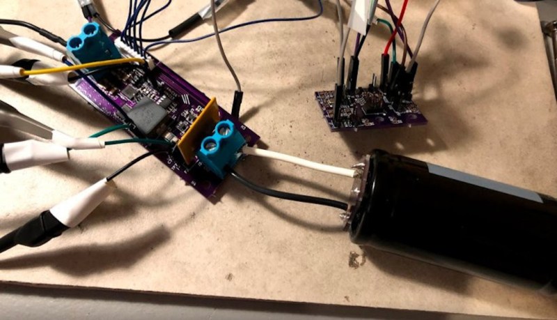
This project from [sciencedude1990] shows off some of the quirks of supercapacitors by showing one method of rapidly charging one. One of the most critical differences between batteries and supercapacitors is that supercapacitors’ charge state can be easily related to voltage, and they will discharge effectively all the way to zero volts without damage. This behavior has to be accounted for in the charging circuit. The charging circuit here uses an ATtiny13A and a MP18021 half-bridge gate driver to charge the capacitor, and also is programmed in a way that allows for three steps for charging the capacitor. This helps mitigate the its peculiar behavior compared to a battery, and also allows the 450 farad capacitor to charge from 0.7V to 2.8V in about three minutes.
If you haven’t used a supercapacitor like this in place of a lithium battery, it’s definitely worth trying out in some situations. Capacitors tolerate temperature extremes better than batteries, and provided you have good DC regulation can often provide power more reliably than batteries in some situations. You can also combine supercapacitors with batteries to get the benefits of both types of energy storage devices.


I’ve read the article 3 times and looked at all the hackaday.io blog logs but it’s not entirely clear what this project is trying to do. Creating a 6A constant current source using a PWM like charge mode?
Hi mime,
Charging any device (battery, supercapacitor) usually needs something between the wall plug and the device. Supercapacitors give challenges because when discharged, they look like short circuits so the overcurrent limit will trip on the wall plug. Also, because the capacitance is so high, it can lead to instability in the wall plug output (typical wall plugs might tolerate 1 mF).
Another issue is that wall plugs with high power output tend to be 5V or 12V outputs, whereas the maximum voltage on the supercapacitor is 3V for this brand.
Lastly, you want to charge this efficiently (i.e., keep the components from overheating). So, you start with something like 12V 1.5A coming out of the wall plug, and you change it to 3V 6A using the switching circuit.
Cheers, David.
Here is the follow up project – i.e., what was the point of charging up the capacitor… :)
https://hackaday.io/project/174850-stop-dead-batteries-for-wireless-controllers
Great use! I hate battery corrosion in my seldom used remotes!
Did you find any caps that would fit into an AA battery slot? That dc step up is small and only $2.79 from mouser.
It would be cool if it could all fit into 2AA batteries. Then you could move it from device to device.
You *might* be able to squeeze this in…
https://www.digikey.ca/en/products/detail/avx-corporation/SCCR25E505PRB/7595400
But then it is 5F, so run time would be a couple of minutes. I think the best bet is to have a module, then 3D print adapter plates (see the xbox proof of concept photo).
All we technically need to do this is a P-channel transistor, an inductor, a diode, a 555 timer, and a pair of comparators, a pair of potentiometers/trimpots and a latch. And of course a current shunt…
The 555 timmer will be used to create our clock to drive the circuit.
It triggers our latch.
The latch turns on the Transistor.
The transistor feeds current into our inductor that will also stop any excessive “inrush” from happening.
The current going into our super cap.
And on the low side we measure the current flow out from it with out shunt.
We measure the voltage on the shunt with a comparator, when it reaches a threshold, set by our potentiometer/trimpot. Then the comparator turns off our latch.
Our latch then in turn turns off our transistor.
Our Inductor will try to force current to flow regardless, this is where our diode comes in. (It sits between our ground and the output of our transistor.)
Current will now flow through our diode.
After a while, our 555 will turn the latch back on, repeating this whole cycle.
The 555 frequency will need to take into consideration that we our technically only driving our circuit up to a set “peak current”. So on load release, our inductor will still need to dump this residual energy into our cap. But this is in general a very small amount of energy. (A single Joule at most…)
To stop this infinite cycle from happening.
We use our second comparator to sense the voltage on the output of our inductor. (Ie, the voltage between ground and the + terminal of our cap. (and also the voltage over our shunt, but that is small.))
When this comparator triggers, based on a set point provided by our second potentiometer/trimpot, then it will inhibit the 555 timer itself.
Also, disconnecting the capacitor will re initiate the circuit, our output voltage will drop, our 555 starts once more, and out latch will turn on. But since current won’t flow between our output terminals, then our latch won’t ever turn off, unless we connect a new cap, or some other load. (So the output is a bit “unsafe” in this regard.)
But this is frankly not a hard thing to build in the slightest….
If we do not care about efficiency, then we can just as well use a power resistor.
or we just get a linear or step down converter with built-in current limiting. If you get a “simple switcher” such as the randomly picked lmr12010, you need one active component and 8 passives.
https://www.ti.com/lit/ds/symlink/lmr12010.pdf?HQS=TI-null-null-digikeymode-df-pf-null-wwe&ts=1600328960918
I think the issue with the diode from ground to transistor output is that it may be difficult to scale up the current. Even a low forward voltage Schottky diode might start dissipating ~2W at 6A. With the right mosfet, I think you can get close to 1W even at 20A with the right combination of rds and gate charge.
Yes, the forward voltage of a diode is generally going to decrease overall efficiency.
A low side transistor is indeed preferable thanks to it’s lower effective forward voltage. Though, transistors have the downside that they need power to run, so in low load scenarios, they can end up chewing more power than just a diode.
But logically, we can replace the P channel transistor with a half H-bridge chip. (Where the “max voltage” comparator also turns on the output inhibit of the half H-bridge, as to not have it create a “short” to ground if left in a low state. (If left in a high state, it will instead create a surge in current and make our voltage go through the roof instead…))
“I can do this with a 555” ;)
Effectively yes.
Though, we could just as well use a bi stable oscillator made of 2 NPN transistors, 4 resistors and a pair of small valued ceramic caps….
Or a HEX inverter chip tied into a 5 inverter oscillator. (Any odd number leads to oscillation, too few oscillators leads to instability.)
We could also do some LC tank circuit with a transistor to keep it going indefinitely.
Or just an off the shelf oscillator.
In short, I don’t really see much need for a whole ATtiny13A for a simple constant current buck converter.
But this is actually a very small, low cost micro, that honestly does do the job decently enough, and is potentially more cost effective than my proposed solution, due to having fewer components, thereby also using less board space.
It’s so huge for half a Wh.
They are huge and you could make the entire thing lossless and it would still be huge. I don’t know how you get around that and make these things usable seeing it’s just and area / spacing for two plates. Get down to near atomic levels with the gaps??
That is the beauty of the ultracapacitor, the capacitor thickness is on the order of a few angstroms, and the activated carbon surface provides very high surface area. This is why the energy density is so much higher than traditional capacitors.
They shine in a few areas, power density (10’s of kW/kg), charge cycle life(500,000), low temperature performance (down to near -40C), and the ability to discharge to zero V without damaging the cells. There are efforts to improve the energy density, but these are not electrochemical batteries and aren’t going to compete on energy density.
Thats pretty wild. I’m amazed at the spacing on ceramic surface mounts lol.
A 1 Farad capacitor holds 1 Coulomb of charge per Volt of electric field between its plates. 1 Ampere is defined as a flow rate of 1 Coulomb per second. If you discharge a 1F capacitor at 1A, the voltage between its plates will fall by 1V per second.
To stretch that out to 1V per hour, you’d have to reduce the discharge rate to 1/3600A or 278uA. In battery jargon, a 1F supercap discharging by 1V is roughly equivalent to a 278uAh battery.
That puts a 450F supercap about the same level as a 125mAh LiPo, or half a CR2032 coin cell (nominally 240mAh).
Supercaps are neat, and can be useful, but their energy storage is still a couple orders of magnitude below chemical batteries.
A good point. However storage density is only relevant in some situations though – for instance under my desk I have a UPS with a lead acid battery that should last that 10 mins or so (save and shutdown not off grid stay up), but where it sits under the desk is the space to put a UPS about 10x the volume, maybe a little more – and if a supercap UPS was what I had I could easily put it in an even larger space if needed the space under the desk in my case is there. While it being smaller is nice, it really isn’t needed and as the automatic dump all memory to disk power off doesn’t take any more than a min the fact the battery lasts hugely longer than that is kind of pointless and at some point soon I’ll have to replace the battery again..
Same thing with something like an LED torch – only so small it can get before it becomes uncomfortable to use in our human sized hands, and only so long you really need light for. So for many situations that torch body full of super capacitors could be used – won’t say its better than a battery, as its not in many ways, but there is a niche for capacitor powered devices and further uses as the go between to smooth out demands a battery can’t take.
I’d like to see more devices where the bulk to store enough power matter little using capacitors – put batteries that are much harder to recycle and don’t last only in the devices where they are really needed.
Capacitors are indeed nice devices for when energy density isn’t a major concern.
The main advantage is their insane power density.
After all, as Mike has stated, a 450F super cap is equivalent to a 125mAh LiPo.
A 125mAh LiPo battery charged to lets say 3.8 volts, would only give us 12 watts, if discharged at 25 C.
While our 450F capacitor would happily provide us 10+ amps at 2.5 volts. Ie, 25+ watts.
For an example, if we use this capacitor in our UPS: https://www.digikey.se/product-detail/en/tecate-group/TPLH-3R0-450SS35X71/2085-TPLH-3R0-450SS35X71-ND/9930287
It is “cheap”, can store 2.5 (or 3 volts) volt for “10 years @ 25C.” according to the manufacturer.
It has a rated current of 287 amps.
If we are a bit conservative and only use lets say 150 amps, at 2.5 volts, that is 375 watts.
Though, the capacitor only stores 1400 Jouls, so at 375 watts, it won’t last many seconds.
But if we have a bank of lets say 10 of them, then a computer setup consuming lets say 400 watts, (monitors, and PC included + maybe networking too.) then our 14 kJ capacitor bank would last a short 35 seconds.
So as a UPS, it isn’t “ideal” unless one is really quick at saving.
Though, if we double the capacitor bank size, and also stop the computer from running any heavy tasks, then we could likely also halve our power consumption. Thereby getting up to a nice 2 minutes of up time.
Then we have the leakage current though, it is 1 mA per capacitor, so 20 of them would consume .05 W if we keep the bank charged to 2.5 volts. Question here would be if the self discharge rate of a lead acid battery is higher or not?
In short, it would do as a UPS. But maybe not the most practical thing. Unless we need an absurd amount of power for a short amount of time, so they could compliment a battery bank non the less.
UPS tend to trigger the shutdown state automatically as the computer is aware of the UPS charge state – so all it needs to do is last long enough to trigger and have the shutdown finish (and doesn’t need to power anything but the PC itself in theory). As you quite correctly point out they can provide the peak power with ease, but do lack the endurance – Should however be fine if you are using your UPS to prevent work loss and damage not as a real battery backup power supply.
With the expected lifetime on Caps if I’d been able to buy a Capacitor based UPS I’d not need to have replaced anything at all. Where the Battery UPS has been through I think 4 batteries since new now – the depth of discharge when the power is out is pretty significant so when the power is iffy it doesn’t take long to need a battery change – abusing the battery really (should probably have sourced a larger one – but this one had the combination of decent brand (so expected good quality and as its still going I’d guess it really is) and cheap)).
As for the self discharge rate between the two a very good point to which I don’t have a clue on though I’d suspect the battery does better by a fair margin. For the purpose of a UPS however its pretty irrelevant – the point being to protect your data and equipment.
Yes, a good UPS should inform any connected hardware that “power is out!” and get everything to shut down. (if just used as a “graceful” shutdown during a power outage.)
Though, if we size a UPS solution with enough lead acid battery capacity, then we can largely run without worry. And deep cycling shouldn’t be too much of an issue since we could discharge at a low C rate, thereby also get better discharge efficiency.
Most small UPS solutions tends to “over discharge” their batteries, mainly by having very large power output compared to the battery capacity. (A 1.5 kW UPS might only have a 400 Wh battery in it. Leading to a rather aggressive discharge)
Then there is the fact that most “small” UPS solutions have no cell monitoring/balancing. And lead acid cells hate to be in a discharged state. They build up a layer of lead sulfide, that flakes off and build up at the bottom of the battery, eventually leading to a short… If not discharged deeply enough, this sulfide layer doesn’t get thick enough for it to flake off, thereby extending the battery life to “infinity”, on paper at least.
But without monitoring, the smallest cell tends to be the week link and die first, bringing the rest of the cells with it, since we can’t easily swap only the bad cell.
So battery based UPS solutions tends to have these failure points.
I know some larger UPS solutions for things like hospitals and data centers can at times have battery monitoring, so that the technicians can simply swap the “bad cells”. (usually whole 12 volt batteries, but there is strings of them, usually providing a combined voltage of about 300-450 volts.)
These UPS solutions are typically rated for between 25-45 minutes of continuous operation at peak load. As to give time for generators to start, and give margin for generator failure. (If sufficiently many generators fails, then some UPS solutions can make an automated call to a nearby generator leasing/renting service specializing in providing building power. (This is likely rather rare, but if the service exists, then one can save in on the space and maintenance costs of a whole generator, far from an insignificant amount of savings, especially in a densely populated city.))
I have though seen some lead acid battery balancing/monitoring chips on the market from some chip makers intended to be installed inside battery packs. Though, all chips I have seen have been made with 4 cells in mind. Not the common 6 cells of 12 volt batteries….
So the largest weakness of lead acid cells might “soon” disappear in some “higher end” batteries on the market. But I guess there will be a premium price on these….
Though, would be wonderful if there were a hot swap, balanced lead acid battery standard on the market. Since lead acid cells are largely maintenance free, loves being fully charged, easy to recycle, and cheap. Unlike Lithium that is twice as expensive and hates being fully charged 24/7, and the weight advantage of Lithium is largely pointless in the vast majority of UPS systems.
But these “small” home UPS systems that frankly are too small to efficiently keep a system running, could indeed benefit from using capacitors. Even if they might up front cost twice as much. (Super caps are after all rather expensive per Wh compared to batteries.) But if that up front costs means that they can work “flawlessly” during 10 years, then it would make sense if one knows that power will drop out at least once a year.
lithium titanate batteries are very similar. I believe they can technically survive a 0v discharge or two, but they’re not meant for it. However they do have a linear ish curve between about 2.2 and 2.6v.
They can dump huge amounts of peak pulse current, they last for 20k cycles, they can float charge, but their energy storage is much better than any capacitor, and I believe has even been used in electric cars. I think it’s like 1/4th of lithium ion’s power density or something.
Super hard to find in the US, but you can buy them on Aliexpress. I’m building an Arduino compatible RF board with mine, when I get a round tuit.
I still wear a wristwatch and it used to feel like I was always having to replace the battery. On at least two occasions, I took the watch in to have the battery replaced and I was told the watch was broken. Was it broken before I got there, or did the battery person break it? I don’t know.
Twelve years ago I got a Citizen Ecodrive. Its whole face is a solar panel, though it doesn’t look like it. The solar panel charges a Lithium Titanate battery. This watch has been running nonstop for 12 years and I wear it every weekday. I’m really impressed, as you can tell.
I also have a solar powered casio, but it gets really annoying in winter, because cold weather jackets have longer sleeves and it gets tucked away and sometimes discharges due to lack of light…
Indeed! Seiko’s Kinetic watches use the wearer’s motion to provide the energy for their quartz movements. An internal pendulum drives a generator to charge a storage unit which supplies electricity to the rest. They originally used supercapacitors but the ones they chose had a limited lifetime and only provided a reserve of days or a few weeks without movement. Now they use a drop-in replacement lithium titanate cell which has a longer life and a six month reserve without motion. Nice! (By the way, for nerd credit – you can find US$350 or so Kinetics cheap because their supercaps have failed. Replacing them with the new cell is straightforward and fun. That’s how I got mine.)
Oooh I didn’t know anybody used Kinetic capture to power quartz watches.. That said for me its hard to beat a real mechanical – might not be as accurate but the mechanism is so much more visually impressive. (Also the last few quartz watches I wore wouldn’t keep time on my wrist at all – never did figure out why as for those occasions I need a watch I have Grandfathers wind up mechanical one – which still keeps time pretty well though definitely should be serviced…)
I chose the Kinetic for the accuracy (1/3 the drift of any quartz watches I’ve owned before: 190ms/day), waterproof to 100m, sapphire equivalent crystal (no scratches!) and no worry about future battery availability or hassle. The transparent back and view of the mechanism is as good as any automatics I’ve seen. Also utterly silent and no second hand overshoot each second. Not bad for US$45 and a bit of work for one that looks new.
I have a Citizen Ecodrive dive watch. I had to replace the battery after around ten years, as it would hardly get to a full charge anymore and if it got there, would lose it quickly. Replacement was cheaper than expected and I hope to get another ten years out of it.
Ah, lithium titanate, that makes sense now. I was wondering how mine worked, because it seemed to have too many cycles for a battery and too much power density for a cap.
My sample size is only 1, but they do seem to die if left in a discharged state for too long e.g, months. If you have an eco-drive watch that you don’t wear much, make sure to leave it face-up somewhere with regular light.
Have you had a look at the current spec of such a thing?
Just a random pick: Samwha DB0E407M35060HA, rated at 400 F/2.5 V is rated at 25A continuous/214.2A peak current.
They complement very nicely batteries, that’s their strong point!
Super capacitors compliments batteries very well within pulsed power applications.
Where we require high peak power, but only for a few seconds at most, like in an electric car.
Though, I have seen very few electric cars that have an actual capacitor bank in them, even if a simple 30 kg capacitor bank stores about the same amount of energy as a 1 ton vehicle has in inertia when traveling at 110 km/h.
A capacitor banks main advantages is its high power output, but also its very low charge/discharge losses.
Something that would make regenerative breaking more lucrative in electric vehicles.
One downside at the moment is their relatively low energy density. not that I suspect that they will ever actually compete with batteries, but they do indeed complement batteries exceptionally well.
Though, super caps also have 1 major downside, their MTBF values are laughably low. Like 2000-6000 hours at 65 degrees C and full charge isn’t “impressive” in the slightest. (Though, in practice, the capacitor bank wouldn’t be left at full charge for more than a few minutes at a time. And rarely above 40 C for that matter. (Ie, we would only keep energy in it when we expect to need it within the next couple of minutes, like at a red light. And we can also keep it less charged than “max charge”, as to extend its working life even more.))
Only 6000 hours? This is new to me. Does this hold for supercaps with 500k discharge cycles?
Super caps (and electrolytic caps in general) tends to dry out over time, and in effect get higher ESR as a result. And the capacitance can also drop. (The capacitance can also increase at the “end of life”, due to the film layers internally getting closer as the electrolyte drys and shrinks, but the ESR tends to go through the roof!)
But it is as stated dependent on the electrolyte drying out, not on charge cycles. (though, rapidly charging and discharging it will make it heat up, and thereby the electrolyte drys faster. (and if heated enough, it can even boil and the whole thing exhibits catastrophic failure.))
Though, 6K hours at 65C is a very good MTBF value for super caps.
Some can be as low as 1000 hours. (some though “cheat” by stating their MTBF at 25 C, getting numbers in the 40k+ hours…. Since the rate that electrolyte drys out is proportional to temperature. (a rule of thumb is twice the rate for every increase of 10 C.))
Also, “MTBF” is Mean Time Between “Failures”. Where a “Failure” isn’t that they drop dead, but rather exit spec. (Typically lose 20% capacitance, or increase their ESR by X%. But dropping dead is also a failure.) Depending on the application, this “exit of spec” might be largely unimportant.
But compared to “normal” capacitors that have MTBF values in the 10-25K hours at 85-125 C is making super capacitors look a bit “bad” in comparison.
Also, a lot of capacitors can be left at full charge at room temperature for a fair few years without much degradation.
Great waveforms/info!
The first time I saw a 12F capacitor advertised in a Fry’s ad, I thought it was a misprint. “No way those don’t exist”. After realizing this space-age tech was real, I laughed because their purpose was to keep headlights from dimming to the beat of a high power stereo system!! LOL
That is a awful lot of hardware just to charge a super cap. There are many IC on Digikey that are designed to do this same thing.
Hi Mike – it is true. If you want to do linear charging, then you can get single components. Such as the LTC3225:
https://www.digikey.ca/en/products/detail/analog-devices-inc/LTC3225EDDB-TRPBF/1931591
However, at 150 mA charging, it tends to get a bit hot.
The switching topology lets you efficiently charge the capacitor where the power at the end of charge is in Watts. See the first page of the datasheet for the LT3741 for a 20A version:
https://www.digikey.ca/en/products/detail/analog-devices-inc/LT3741EFE-PBF/2225684
Cheers!
I charged two supercaps in series with a lipo charge ic and passive balancing. Added a diode in it’s ground path to raise the charge voltage from 4.2 to ~4.7v. Not very nice, but works well in the field
How did you add a diode in the field? Is there an easy spot to put it? (Trying to figure the circuit diagram)
You can easily make super caps with beer bottles, a 5 gallon bucket and mineral oil.
Size is ultimately the issue behind why everyone is “excited” by super capacitors.
Supercapacitors with just aluminium and mineral oil? How?
u have to limit to 1.2v, right, but the amount of amps your allowed is infinite! so u charge it with 200 amps, the capacitor can take it!!! then u can get it done in a second!