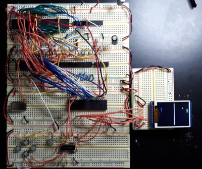
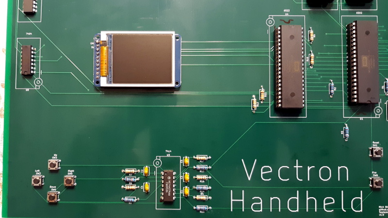
Recreating the arcade smash hit Pong in a device small enough to plug into a home television was a considerable technical challenge back in 1975. Of course, a big part of that was the fact that it needed to be cheap enough that consumers would actually buy it. But had money been no object, the Vectron Handheld by [Nick Bild] shows what a dedicated Pong board based on the 6502 CPU and 7400-series logic could have looked like.

Well, aside from the display anyway. While [Nick] made sure to use components that were contemporaries of the 6502 wherever possible, he did drop in a modern SPI LCD panel. After all, it’s supposed to be a portable game system.
Though as you can see in the video after the break, the massive 273 mm x 221 mm PCB only just meets that description. Incidentally, there’s no technical reason for the board to be this big; [Nick] was just playing it safe as he’s still learning KiCad.
Those with a keen eye towards 6502 projects likely saw the breadboard version of the Vectron that [Nick] put together last year. Compared to the original, the circuit for the handheld has been considerably simplified as it wasn’t designed to be a general purpose 6502 computer. Whether or not you think being able to play Pong on it makes up for those shortcomings is a matter of personal preference.


So, on the left side of the display, he needs to press the “down” button to move the paddle up, and on the right side vice versa…
No, the left side is computer controlled. The right side is the player — and down is down, up is up.
Oh! Okay!
I didn’t listen to the audio on the video clip.
Hmm, I wonder about how much time the CPU spends writing to SPI vs. doing anything else?
Writing a full screen is expensive, but moving around some sprites isn’t bad. I had to put in a do-nothing loop to slow down the game, actually.
Why is the pcb 4X larger than it needs to be? Not exactly handheld. Even the breadboad was about 1/4 of the size.
It’s so the auto router could find a solution I bet
He outright admits to this.
>this was my first crack at designing a PCB
KiCad has no auto-router (so far as I can tell, anyway). It was so I could find a solution. :)
as far as I remember, there is an add-on or an external tool that provide for autoroute.
I would imagine if most of us, especially those who are engineers, but not EEs, would look at our first boards we’d think similar. His next step is making it smaller. Easy. The hard work is done.
you cant play pong properly with buttons.. where are the Pots? – then that ‘do nothing loop’ can be removed too :)
The SPI *could* have been a few times faster if it were hooked up to the CPU bus directly vs bit-banging the SPI using GPIO. The 6502 bus is relatively slow (~1MHz possibly) vs (a few MHz) LCD, so you can easily hook up the SPI to the CPU bus directly.
– a chip enable can be used as the serial clock pin while a data line e.g. D0 is used for data.
This way each write to the address automatically strobe the serial clock line and it can latch the D0 on the termination of the write cycle (rising clock edge). easily a factor of 3X vs individual cycles just to set GPIO for: CLK Low, Data, Clock high
“The W65C02 is clocked at 8MHz.”
oh! nice idea, I’ll keep that in mind.
True. I’ve done that before, see Vectron VR: https://hackaday.com/2019/06/23/vr-on-the-6502/
It makes the address decoding circuitry grow though, so I didn’t do that here.
Oh, I remember these early telegames consoles from the fleamarket.
Very interesting!
From what I read, the early models had no CPU at all.
Instead, they were either using simple digital circuits (TTL) or were entirely analogue (!)
Also fascinating were the early colour models (70s).
They created a colour gradient as a bsckground.
100% analogue, by utilizing flaws of NTSC or something along these lines.
Not sure if this was possible on PAL, too.