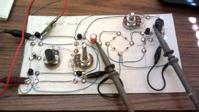
A synthesizer without transistors could almost be the basis of a trick question, surely without transistors it must be using a vacuum tube or similar. Not [Dr. Cockroach]’s synth though, instead of transistors it uses coupled pairs of LEDs and light-dependent resistors as its active components. Its oscillator circuit comes courtesy of [Patrick Flett], and uses a pair of LED/LDR combinations to alternately charge and discharge a capacitor. This feeds another LDR/LED pair that appears to act as a buffer to drive a bridge rectifier, with a final amplifier following it.
The result oscillates, though at frequencies in the low audio range with a cluster of harmonics thrown in. Its sound is best described as something akin to a small single-cylinder motorcycle engine at the lower frequencies, and is something we see could have all sorts of interesting possibilities.
This approach of using LDR-based active devices may be something of a dead end that could have had its day back in the 1930s, but it’s nevertheless an entertaining field to explore. It’s not the first time we’ve followed [Dr. Cockroach] at it, in the past we’ve seen the same technique applied to logic gates.
Have a listen to the synth in the video below the break.


Nah, definitely a four cylinder.
I think it’s the new sound of the Harley LiveWire.
Reminds me of the vacuum tubeless/semiconductorless amplifier of days gone by: The carbon microphone. It had so much gain, it too could be made to oscillate acoustically with a battery and magnetic earpiece. They also used them to amplify telephone lines by putting an amplifier in line consisting of a back to back carbon mic and earpiece.
Sad to say I had some carbon mics back in the late 60’s and never made use of them….
HOW DO I MAKE THIS OSCILATOR PLEASE SHOW ME I’LL DO ANYTHING
Earlier one sounded more like a stationary diesel, like a Lister clone or something.
A different tap point for the audio perhaps. One tap point has a more metallic sound to it.
VF750c
I just played the video and my 3 year old comes up to me (he couldnt see what i was looking at he was just getting the sound) and quiet excitedly asked. “Is that a motor bike?”
That’s cool to hear about your son :-D
Hey, I know that guy :D Well done, pal!
:-D
Me: Hrm. What about other interesting things that can oscillate, and also interact with electronics? Like, piezo electrics? Or even metal plates?
Friend: [Sarcastic Stare]
Me: What? I’m sure you could make it work. I’d bet thin pieces of metal, or even wires can make some interesting sounds. I’m not sure if they would be pleasant or not. But I’d bet you could tune them by changing their shape/thickness/length.
Friend: [Keeps Staring] [narrows eyes]
Me: No I’m SURE it could work. Why are you looking at me like that? No. Now that I’m thinking about it, there has GOT to be a way to take a metal string, or maybe a spring, and electrically couple it with some sort of sensor.
Friend: You mean like…an electric…guitar? You just described an electric guitar. Or really, a regular musical instrument, but with a microphone pointed at it.
Me: Oh…huh.
Gold! :D
Which one of you have never accidentally to reinvent the wheel can throw a diode.
Now I know what fascinating sounds like…..sounds like it belongs outside…..
Wire the pot up clockwise. It may be a log pot and thus tapering off slower. I think though it needs an audio taper (log) and be wired up clockwise and then the note range will usable end to end. This design looks like a bistable multivibrator.
Quite right. The main oscillator is a form of bistable and the LFO is a astable all using the led/ldr pairs.The pots are audio taper as that is what was in my junk box, linear would have been my first choice . Lots of room for improvement :-)
Damnit Doc !
Now I want one !
Muahahahahahaha
Sounds like a dragrace tuned 100cc four stroke thai motorbike to me. Crazy fast btw…
The bridge rectifier acts as a frequency doubler. Otherwise you couldn’t hear much. The intermediate buffer stage is there to isolate the circuit so the subsequent stages wouldn’t mess up with the tuning.
Actually I have tapped off audio before the bridge and still get the same notes but with a flatter tone. The bridge does double but also creates a load of harmonics as well and that gives the tone a much richer quality.
Hey everyone! I’m the one who created the oscillator circuit. Check out my YouTube channel for more info about it. I’d love to get more info about it out there, but my university classes are really bogging down my schedule. Hopefully soon!
https://www.youtube.com/channel/UCdY0rnioc1twUgD6JwpuXvg
Hey Patrick, welcome aboard :-)
Any plan for a collab with Gamechanger Audio? https://cdm.link/2019/06/motor-synth-gamechanger/
That would be great to pair with a big speaker under the hood of an electric car so that pedestrians can here it coming.
I like the guy who used the sounds of The Jetsons “car” on his EV!
I was looking at the oscillator core. Does the supply voltage across the two LEDs need to be less than the sum of the two voltage drops so they don’t both turn on at once? Photoresisters usually have a very small power dissapation so do the pair of photoresistors need a current limiting resistor?
I haven’t seen vactols mentioned but there are a lot of pages about LED / photoresistor elements out there under that name.
Hi Stephen, this is Patrick. Yes, the supply voltage (across the two LEDs) does need to be below the voltage drop of the two LEDs for the exact reason you specified. I think of it as an overlapping voltage drop. 5V works well for white LEDs.
The photoresistors only get too hot to handle the current when your voltage (across the two photoresistors) is cranked up to a fairly unreasonable value (I maxed out my HP power supply at 40V just for fun, they got fairly hot). I found out that it oscillates much quicker when the two photoresistors are given more than 5V. Unfortunately, you run into the issue of it getting too hot, which causes it to run slower. I feel like there is a happy medium between 5V and 40V that could provide the quickest oscillation without overheating.
Thanks Patrick. Pushing up the LED supply voltage to just under 2x the LED voltage drop should increase the frequency but the recovery time of the photoresistors is going to be the limiting factor.
Another oscillator without semiconductors:
https://www.homemade-circuits.com/neon-lamps-working-and-application-circuits/
Hey Mike, a neon relaxation oscillator was actually my inspiration for the LED+CdS oscillator!
-Patrick Flett
Hi, I’m a sintesis enthusiast, and when I saw your work, I loved it. I’d like to know if you can share the block diagram of your transistor-less sound synthesizer to see if I can recreate it