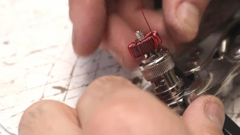
[K6ARK] likes to operate portable, so he puts together very lightweight antennas. One of his latest uses tiny toroids and SMD capacitors to form trap elements. You can see the construction of it in the video below.
You usually think of toroid winding as something you do when building transmitters or receivers, especially small ones like these. We presume the antenna is best for QRP (low power) operation since the tiny core would saturate pretty quickly at higher power. Exactly how much power you should pass through an FT50-43 core depends on the exact application, but we’ve seen numbers around 5 watts.
The SMD capacitors mount right inside a hacked up BNC connector. That makes for a very compact construction at the expense of a little fine work with a soldering iron while building. There is more construction detail on similar traps in a second video that you can see below.
The availability of antenna analyzer equipment makes projects like this easier. The concept of end-fed halfwave has its detractors and proponents. [AA5TB] has a page that explains a bit about the theories surrounding the antenna. Regardless, [K6ARK] says he’s worked the world on this type of antenna and many people swear by them.
Not a ham yet? [Dan Malone] wants you to invest $50 and change that. We suspect, though, you’ll be happier with more wire in the air.


His efhw antenna dosen’t have a counterpoise (or using a coax as counterpoise), so I doubt if it can effective work.
They work quite well actually. No counterpoise makes them more sensitive to tuning variances associated with proximity to ground, so I tune them the way I use them. Performance is similar to a dipole at the same height. With 5w CW, I have worked EU and ZL from California with these antennas fairly regularly from mountain tops in the mornings and evenings respectively.
End fed halfwave antennas, as a general rule-of-thumb, do not need a counterpoise. This is one of their primary advantages and one of the reasons I like using them so much.
Very nice little build. He clearly knew some stuff that he didn’t fit in there, like why 100 pF? (And I’m guessing it must be C0G or similar.)
And my personal hurdle: that dark magic of ferrites. How to know which mix to select, why, and where to get ’em?
That’s rf magic.. thickness, density of iron, quality of filler (is it paramagnetic or diamagnetic?) outside diameter, inner diameter, length, atom count..
The only question I CAN answer for CERTAIN in your comment is when using capacitors ALWAYS UPSTEP the farads and the voltage they can handle and hold and REMEMBER YOU CAN NEVER DOWNSTEP!!! Everything else? Yeah.. smoke that dark magic sauce with the rest of humanity..
Remember this much, YOUR EYES are ANTENNAS that are specialized for a specific range of the Electromagnetic frequency.
“Remember this much, YOUR EYES are ANTENNAS that are specialized for a specific range of the Electromagnetic frequency.”
But not very good at transmitting…
B^)
100 pF seems to be a sweet spot for these antennas when building them for use on higher bands. I’ve used 300 pF in another antenna after experimentation showed a better match with that value on higher bands. For 17m and below, and when using links or traps rather than multiple half-wave lengths of wire (i.e. running 15m on a 40m halfwave wire) you actually don’t need the capacitor at all!
I have purchased toroids from cheap sources on Amazon and direct from Amidon and have not noticed and significant difference in quality or performance. -43 mix certainly seems to work best for EFHW transformers.
Nice article. I agree with Steve (AA5TB) that there is some unintended coupling across the balun inductor which serves as a phantom counterpoise. I also agree that there is no magic about a quarter wave length b/c if you balance the reactances to match the input impedance you can get just about any length to radiate. It’s hard to make an efficient resistive radiator with an isolated transformer which has one side unloaded, therefore the presumption of the phantom coupling across the balun.
I’d love to see the return loss sweeps with the input winding on the opposite side of the toroid core from the output windings.
This is RF, after all, and some of this stuff acts a little different than intended, sometimes to great benefit.
If this was high power, I’d definitely recommend grounding at the coax shield side of the balun (personnel protection from RF power).
I wouldn’t bother with loss and windings.. since you know your science. why haven’t you thought of using a wound straw, inside a wound tube inside a wound pipe, inside a wound tube, inside a wound can, inside a wound barrel.. Oh.. that almost sounds like that’s an extensible antenna.. Hmmm.. if only something was know about how strong nuclear, weak nuclear, gravity and that other one.. had some sort of book and definition that could be figured out.. Or just be accepted be used properly.
Personally, I rather USE my hands.. then just think about the hands.. Understand?
It doesn’t do good to just think about return loss sweeps unless you USE “return loss sweeps”.. or the even have a use.. Do you understand?
Dan, AI6XG, did some interesting experiments with capacitors and these transformers, and loss/efficiency measurements. Check it out here: https://www.ai6xg.com/post/end-fed-half-wave-antennas-more-about-the-primary-capacitor
“Big” SMD caps at normal values and voltages don’t have the capacitance vary much with applied voltage but the tiniest 0102 are practically varactor diodes WRT to noticeable variation in capacitance with applied voltage.
Could be either a problem if unaccounted for OR a nifty remote tuning feature.
Capacitance change with applied voltage is more a function of the dielectric material than the physical size, no?
An 0201 size NP0 or C0G just isn’t going to be able to have much capacitance, so it’s likely that the only caps that size with more than a nF or so CAN’T be C0G types.
My take on QRP is, resonant dipoles is always best, but endfeds are great when antenna trees are far between (like above the tree line in the mountains)
I have worked a lot of countrys on an inverted L endfed, strung up between a fishingpole and some brush vegetation.
Bring a lot of line so you can use tie points far away if you need to slope the antenna really far