For the casual breadboard experimenter with a microcontroller and a few peripherals, there’s little concern over interconnects as a set of jumper wires will suffice. But as any radio amateur will tell you though, at higher frequencies it’s a very different affair. [Ria Jairam N2RJ] has embarked upon a series of videos exploring co-axial cable and its various connectors, and her first offering features the humble UHF connector, sometimes known as the PL259. Though it’s one of the older choices and its design flaws mean that “UHF” is more of an aspiration for it than a reality, it remains a common connector at the lower end of the amateur radio frequency range.
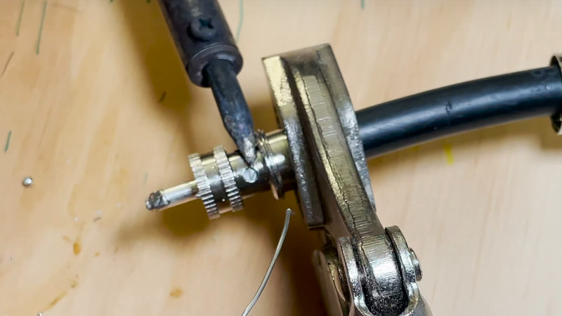
She starts with a brief history of co-axial cable, before introducing the UHF connector. We’re the introduced to its major flaw, in that it doesn’t present a constant impedance. The resulting mismatch presents a significant problem to a transmitter, especially at higher frequencies. We’re then taken through the various different models of UHF connector, including those with honeycomb dielectric to minimize the mismatch, and the fancy expensive plugs with strain relief. Finally she takes us through the proper fitting of a PL259 plug, something that there’s a bit more to than most of us might think. Altogether it’s an interesting and informative watch from an engaging and knowledgeable host, and we look forward to more.
Meanwhile, the field of RF connectors is something we’ve dipped a to into from time to time ourselves.


I put on hundreds of those miserable things in my old job. Hated every minute of it.
Think you added an extra zero there bud.
A PL259 is not the right plug for what it’s used for, but it has sadly become a standard.
If you have a free choice of connectors, a N or SMA will serve you much better, and have done so for 80 and 60 years respectively.
You’re thinking on N connectors.
PL-259s are an abomination. They’re hard to put on right, and they aren’t even waterproof.
259 is notawful about 500 MHz. N gets you out past 10 GHz.
Good start. Looking forward to the N-type video (which I see is already up).
There was the brief mention of the reducer, but no followup on what it’s for or how to use it. (for smaller RG-58 type size cable, but miserable to get installed correctly imho).
Extra tips:
1. Use flux to help tin to avoid the pain seen in the video.
2. Tin the braid prior to trimming and inserting in the connector body: you won’t have to worry about stray strands, the length comes out nice and uniform, and the soldering is very quick: you’re basically just reflowing it.
Reducer? Nah!
Just toss the reducer with the RG-58 into the trash. I used to use that stuff all the time because better coax is so expensive. I didn’t realize just how much signal I was losing. Too much!
If you aren’t made of money just go to hamfests and find something used.
Sometimes tossing them isn’t an option. There were always a couple in the police vehicles I used to build, the antenna mounts used 58 because the coax had to be snaked through the vehicle, and the radios involved needed PL259. We finally got some fairly decent crimp-on connectors to mate with the SO-239 on the radios. Performance was probably just as dreadful but at least they weren’t such a pain to put on the cable.
RG58 is worse than the PL connector, I think.
Better use RG213UBX, RG214, H155 etc.
RG-58, for what I know, has not only loss but also poor shielding by todays standards. In a house or garden, all the noise sneaks into the RG-58 and leads to an S7-9 level of noise. Oh, and also try ferrites. Snap ferrites etc filter coat waves, which are omnipresent in all sorts if electronics. Especially cheap switching-power supplies. Use these ferites wisely and things are much better, I think.
If you can get hold of Messi and Paloni cables their Hyperflex 5 is better than RG58 in every way including flexibility and fitting into tight spaces
Ultraflex 7 and ultraflex 10 are better still albeit thicker (UF7 is slightly thicker than rg8x UF10 is the same size as RG213 but better performance)
Aircell 5 would be my choice
Yeah, tinning the braid helps, but the trick is to get enough heat to get the solder to flow into the braid evenly, without melting the foam dielectric immediately below.
The above is impossible in 40 degree weather.
3. Make sure you leave the jacket long enough so you can screw the connector body onto it before soldering the braid. This is your only strain relief.
4. Don’t forget to put the barrel on before soldering the connector. (can’t tell you how many times I have forgotten to do this)
Perfect timing for me to see this posting. I drilled a hole in the roof of the cab of my truck and installed the antenna mount yesterday afternoon. Now I have to double check the connector that goes on the back of the radio to make sure I have the correct one. I currently am using a mag mount with the wire going out the door. It has been this way for about two years.
Thanks Paul for the recommendation about tinning the braid in the beginning, and the reminder of flux.
Everyone seems to like drilling. When I install antennas (RIP Larsen) on my cars, I like to use a Greenlee punch (3/4″ if memory serves, but maybe 5/8″). Gives a nice neat hole, and if you put the punch inside and the die outside, the lip of the hole is ever-so-slightly pulled out to help keep water out if the o-ring on the antenna mount doesn’t seal perfectly. I always used to use a bit of silicone grease on the o-ring. The other trick I used was to cut a couple of wedges out of 3/4″ lumber, about 6″ long and an inch ot two high. Slide them in between the roof and the headliner to give you a little working space while you’re drilling the pilot hole for the Greenlee and fishing the wire.
In the next (N-type) video she mentions that you can plug the N-type into a BNC socket.
DON’T DO THIS!
Though it LOOKs like they fit, the center contact on the N is larger than the BNC, and will spread the contacts on the BNC socket, ruining it for the BNC male to come along.
You want free mismatch and loss?
That is how you get loss. (and sometimes some carbon tracking and arcing)
Heard it. Decided this wasn’t the place (or the century) to repeat it.
The center pin sizes are the same for N and BNC for the same impedance. The difference in pin size has to do with 75 vs 50 ohm. But I wouldn’t do it regularly. Just in a pinch if I had to.
The BNC center pin mating diameter is 1.32-1.37 mm, irrespective of impedance (the impedance difference is in the OD at the conductor area, and the dielectric)
The N-Type center pin mating diameter is 1.60-1.68 mm for 50 ohms, 0.91-0.94 mm for 75 ohms (which are hen’s teeth — I’ve never seen one).
See the standard in which they are defined, MIL-348. Or see http://www.rfcoaxconnectors.com/technical-connector-interface-drawings.php Or just measure it yourself. Or just look at it: the difference in diameter is plainly visible.
HP’s app note #326 specifically warns warns about mismatching center pin sizes (specifically in mismatching N types, but the same holds for jamming a N into a BNC): […] mating a male 50 ohm Type-N connector […] will destroy the female [smaller] connector by spreading the female contact fingers apart permanently or even breaking them.
Pretty sure the “innards” of a type N are identical to those of a BNC of the same impedance. They were, after all, both designed by the same guy (Neill). The real problem is that a 75Ω BNC has a smaller pin than a 50Ω one and plugging a 50Ω plug into a 75Ω socket will deform the socket.
Sorry: The first and third assertions are incorrect – see my previous comment immediately above.
“Thanks for watching” as Techmoan, one of my YouTube idols says. I started posting videos to teach ham radio topics to others. I’ve enjoyed this hobby immensely and I like giving back :)
73
Ria, N2RJ
Yay! Can’t wait for the next in the series.
With the right tools and a bit of practice, crimping is the way to go. No more soldering connectors for me. de AI6XG
One of my first jobs involved crimp-terminating an ungodly number of BNCs on RG58. Inspection included a 50-pound tug test. I was always impressed how a simple crimp could hold that much force. For the record, though, a crimped BNC won’t usually hold up to swinging Tarzan-style across the shop :-)
Get back to me when you’ve want to talk Type N and all the wonderful variants.
We allways called them “banana plug with union nut”
As it is basicaly not more than this… …even used them sometimes in a banana socked with crocodile-clip-grounding” xD
That’s one of the “good” aspects of UHF connectors, I think.
They are very versatile and easy to use.
You can fix a cable while standing on a ladder or “on the road”. N has better specs, but is like a snobby cousin in this regard. You essentially need a tidy workbench with good light for every little thing that has to do with N.
On UHF, you can use a banana plug of your longwire antenna and insert it into the SO239 socket of your match box. A crocodile clip then can serve as ground connector.
Thanks for the informative videos and I’ve subscribed to your channel. That said, the image of you in the upper right of your Youtube page looks like you’re giving your workbench the middle finger. Also, although it obviously works, your soldering iron tip needs a serious cleaning and tinning. As a retired technician who was required to do repairs to NASA/milspec soldering standards, it made me cringe. 😎
PL-259 / SO-239, sometimes known as UHF
The PL-259 was the first RF connector I ever soldered back in 1981, to connect my DV27 groundplane aerial to my shiny new CB radio. I do seem to remember making a hash of it.