Induction heaters can make conductive objects incredibly hot by generating eddy currents within the metal. They’re used in a wide variety of industrial processes, from furnaces to welders and even heat treatments. [Schematix] whipped up his own design, and put it through its paces on the bench.
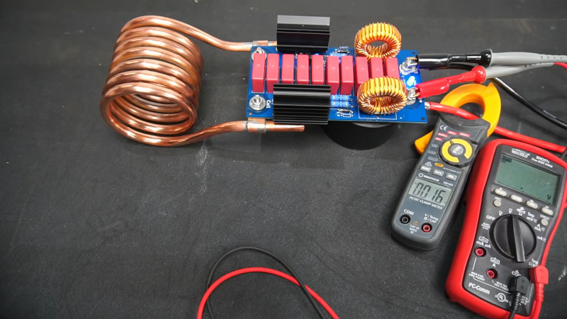
The build in question is a fairly compact design, roughly shoebox-sized when fitted with its six-turn coil. Running off anything from 12 V to 48 V, the heater put out at a massive 1.4 kW in testing. At this power level, the high current draw led the power traces to heat up enough to melt solder, and eventually burn out. [Schematix] plans to rebuild the heater with added copper wiring along these traces to support the higher power levels without failure.
The heater is able to quickly heat ferrous metals, though was not able to meaningfully dump power into aluminium under testing. This is unsurprising, as non-ferrous metals primarily undergo only Joule heating from induction, forgoing the hysteresis portion of heat transfer due to being non-magnetic. However, modification to the design could improve performance for those eager to work with non-ferrous materials.
We’ve seen a few induction heaters before, for purposes as varied as soldering and casting. Video after the break.


Aquarium pump and ice bucket for the coil, notebook blower for electronics. Or ready made unit from usual suspects for half the price.
There is plenty of room on the PCB for wider traces. I think it is possible to build this project without the need to solder extra wires on traces.
Awesome design and demonstration. Great video!
Finally, one I can make! I’ve wanted one of these since I found them as a teenager. I could instantly blacksmith with this if I had one, heat treating oil quench steels would be easy as well.
I’d love to see people post different size coils and ratings for heating different materials effectively
p=ei
14400/48 = 30A
14400/24 = 60A
14400/12 = 120A
You need a pretty substantial power supply to run this at that power level.
Not something you are going to run off a wall wart.
You may also have issued with the heater blowing up if the load changes or goes away in operation. Your garden variety induction hot plate has a microcontroller that supervises it. That is why you get an error if you put a copper bottom pan on it or take a ferrous pan off of it, instead of letting the smoke out of the power switching devices.
Check the HP server PSU’s that people use for Crypo-mining and wherever a lot of power is needed. I have some that produce 12V at 100A. Great for stepper and servo motors. https://www.ebay.com/itm/HP-Proliant-G6-G7-Server-1200W-PSU-Power-Supplies-438202-001-440785-001/233669400236?epid=21025371484&hash=item3667c816ac:g:eNoAAOSwsKFfKDhl
Nice info both of you
There is another way. Build a linear power supply around a buck/boost transformer. By rectifying the buck/boost lines to DC, you get a high surge, high current DC power supply. Now you just need a high current rectification circuit. It also will avoid any high frequency chopper interference.
I like the self-oscillating design. However the usage of PCB for the tank circuit and switches is a bad idea. Just use point to point connections with 1mm thick copper tape and PCB for driver part of the circuit…
Just curious. Where do you find 1mm thick copper tape?
I would not call it tape but sheet metal. But I also have 2mm (by 10mm) thick copper “tape” – I would call it rail or bar :-)
When I saw the video and the guy tinning his puny traces – in comparison with the nice copper tube – I immediately thought: “That is no good idea”. Solder has 1/10 pf the conductivity of copper, so the onlky way to go is to use copper on the traces and not too little. Solder some heavy gauge wire on the traces, at least 4mm² or 6mm²
> non-ferrous metals primarily undergo only Joule heating from induction, forgoing the hysteresis portion of heat transfer due to being non-magnetic
This is crucial. I wasn’t aware that hysteresis loss was so important for ferrous metals. So, even different steel alloys would heat up differently?
Yep, and that’s why heavy stainless steel pots and pans that don’t integrate a chunk of iron into the bottom don’t work on an induction hot plate.
I’ve always wondered why- thanks!
So it will run on 12v? If I wound the copper coil differently (flat) could I make an induction cook top for my car or camper?
It runs on 12V, but with much less power. You probably should lower the impedance of the tank circuit for 12V operation.