
In the fantasy world of schematic diagrams, wires have no resistance and square waves have infinitely sharp rise times. The real world, of course, is much crueler. There are many things you can use to help tame the wild analog world into the digital realm. Switches need debouncing, signals need limiting, and you might even need a filter. One of the basic elements you might use is a Schmitt trigger. In
In this installment of Circuit VR, I’m looking inside practical circuits by building Schmitt triggers in the Falstad circuit simulator. You can click the links and get to a live simulation of the circuit so you can do your own experiments and virtual measurements.
Why Schmitt Triggers?
You usually use a Schmitt trigger to convert a noisy signal into a clean square digital logic level. Any sort of logic gate has a threshold. For a 5V part, the threshold might be that anything under 2.5V is a zero and at 2.5V or above, the signal counts as a one. Some logic families define other thresholds and may have areas where the signal is undefined, possibly causing unpredictable outputs.
There are myriad problems with the threshold, of course. Two parts might not have exactly the same threshold. The threshold might vary a bit for temperature or other factors. For parts with no forbidden zone, what happens if the voltage is right at the edge of the threshold?
A Schmitt trigger input is a bit different. It has two thresholds. One threshold is how much voltage it takes to trip the input from a zero to a one. The other threshold is how much it takes to trip a one to a zero. For example, if an input starts at 0.3V and starts rising a Schmitt Trigger inverter will see that as a zero and output a one. As the input passes, say 2.5V, the output will shift to a zero because the input is now a 1. So far, this is just like a normal gate. The difference is when the input begins to fall. When the input is at 2.4V, a normal gate would have already flipped the input to the opposite state. The Schmitt trigger, though, will maintain a one until the input crosses the second threshold. Perhaps that’s 2V.
This is very similar to a home thermostat. If your heater is set to warm the house to, say, 70 degrees, it won’t turn on at 69.9 degrees. The temperature will have to fall a bit before the heater will kick on and return the temperature to 70. This is known as hysteresis. Technically, the term refers to the dependence of the state of a system on its history. In order to predict the output of the Schmitt trigger, you need to know both the input voltage and the previous input state. In a way, it is an analog version of a simple state machine.
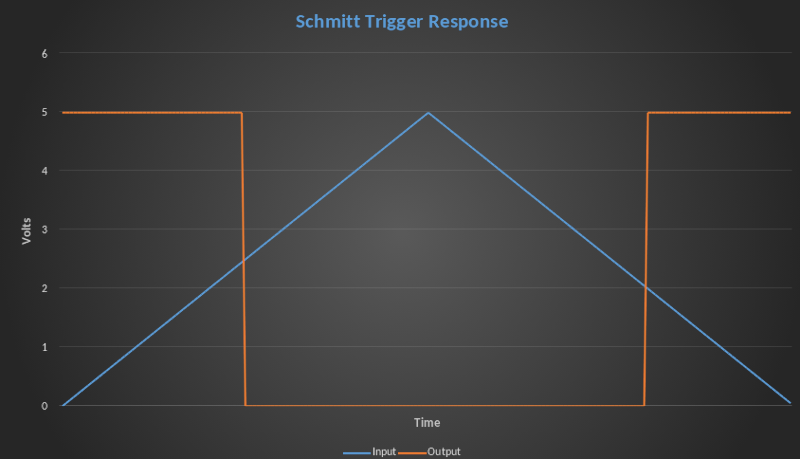 Here’s a graph showing a signal slowing going up to 5V and then back down to zero. The square trace is the output of a Schmitt trigger inverter with thresholds of 2V and 2.5V. Of course, in real life, the output won’t really be that sharp, but it will be fast and compatible with other logic signals.
In Practice
In practice, you might use a Schmitt trigger to read an RC circuit or clean up the input from a noisy sensor. Driving any sort of capacitive load will interfere with the rise time of a signal and that can lead to problems with digital circuitry, especially if you are dealing with a logic family that has a forbidden region between the high and low thresholds.
Most often, you’ll simply buy an IC to add a Schmitt trigger. That’s usually a package of inverters, but you will find other gate types that have Schmitt trigger inputs. They are also common on certain pins of microcontrollers that expect to connect to noisy signals. You can also create a Schmitt trigger out of op amps, or the ubiquitous 555 timer IC. However, for this post, we’ll use good old transistors to get a better sense of what’s happening. As usual, there are several ways to do things, each with their own tradeoffs.
Simulation
To start, consider a simple inverter with one transistor. In theory, the transistor is either off so you basically have a 5V pullup resistor to the output, or it is in saturation, so the output is a few tenths of a volt. If you feed a nice square wave into that circuit it will do just fine. But if you send in a noisy sine wave, you’ll get lots of hash at the edges of the output.
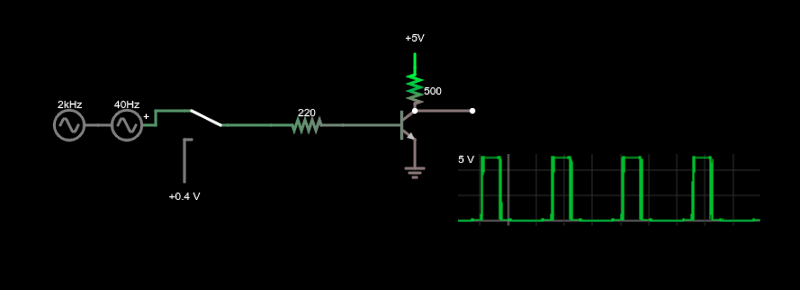
 The simulation has two possible input sources. If the switch is down, the input will be a voltage you can change with a slider on the right side of the simulation screen. If the switch is up, you’ll get a noisy sine wave. We’ll use that particular input arrangement for all the example circuits.
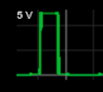
The scope trace is a bit hard to see, but blown up you can see the edges are very noisy as the transistor switches in and out as the signal goes through the threshold of about 0.7V. This is why we need a Schmitt trigger.
First Take
The Falstad examples have a simple Schmitt trigger, so I borrowed parts of it to come up with the first attempt of cleaning up those edges.

That looks much better (although this one does not invert). How does it work? The keys are the feedback from the emitter of Q2 to the emitter of Q1 and the operational modes of the transistors.
If you hover over a transistor in the simulator, it will report if the transistor is in cutoff, saturation, or forward active mode. Just look in the bottom right corner of the simulator while the mouse is over a transistor.
- Cutoff is just what it sounds like. The transistor more or less disappears.
- Saturation is when the transistor is maxed out on collector current. More base current doesn’t really change anything and the voltage between the collector and emitter will be close to 0V but not quite. In this mode, the transistor acts like a closed switch between collector and emitter.
- Forward Active mode is where some amount of base current causes a certain amount of collector current to flow. In theory, the ratio of base current to collector current in this mode is the transistor’s beta, but as long as beta is high, you typically don’t care about it since the circuit doesn’t rely on a specific value of beta. Since beta varies wildly depending on many factors, you usually depend on the voltage through a resistor to set a lower current that you can control precisely.
Three Regimes
These are the three regimes this circuit operates in: Q1 turned off, Q1 saturated, and Q1 in the active region. As a refresher, a transistor turned off will look almost like an open from collector to emitter. In saturation, the transistor will be very close to a short circuit across the emitter and collector. The collector voltage will be just a few tenths of a volt higher than the emitter. In active operation, though, the current in the collector will be proportional to the base current.
If Q1 is off, there is more or less a 1/3 voltage divider against 5V to the base of Q2. That’s not exactly right because the base of Q2 adds some resistance, but since it is relatively high you can ignore it. So you get about 1.5V on the base of Q2. That will turn on Q2 bringing the output down to a low voltage. Just as important, the saturated collector current through the 100Ω emitter resistor will keep the emitter node at just under 0.9V.
If you want to verify that, pull the switch down and set the slider to a voltage that cuts Q1 off, say 0V. Because the emitter voltage is at 0.88V, the base of Q1 will need to reach around 1.5V to get Q1 to turn on.
The second regime is when Q1 is saturated. It is easy to see that since the collector will have a very low voltage, it will turn Q2 off and the output will just be the pullup resistor to 5V.
If you start increasing the voltage, Q1 will eventually move to the forward active stage. This won’t have much effect on Q2’s voltages, though. There is a slight increase in the emitter voltage which causes a slight increase in output voltage, but that never exceeds 1V.
So things stay mostly the same until Q1 saturates at 1.47V. You may want to edit the voltage source instead of using the slider to get that precise. Also, don’t forget, if you slide past the threshold, you have to reset to zero (or, at least, below the low threshold) before setting the voltage since we are looking for a rise in voltage, not just the arbitrary value.
At 1.46V, Q2’s base is still at 1.5V and the emitter node is still at 880mV. The output is under 1V (984.8mV). At 1.47V input, Q1 saturates and Q2’s base is now under 650mV. The emitter voltage goes to about 815mV.
As input voltage continues to increase, Q2’s base and emitter voltages increase as well and Q2 stays cut off. So what happens if the input voltage drops back to 1.46V? Not much. With Q1 in saturation, it stays in saturation. Note the emitter voltage is now almost 80mV lower than before, so it is easier to keep Q1 in saturation. Since the emitter voltage is dropping with the input, though, you can expect a 40mV drop, roughly, would put things back to the opposite state. At 1.06V, the circuit flips Q1 off again, and you are back to the original state. You can see this summarized in the table below, where 1.46+ means voltage rising to 1.46 and 1.46- means voltage dropping to 1.46.
| Input | Q1 | Q2 | Q2 Base | Ve | Q1 Vbe | Output |
|---|---|---|---|---|---|---|
| 0.10+ | off | sat | 1.531 | 0.878 | -0.778 | 0.949 |
| 1.46+ | act | sat | 1.531 | 0.880 | 0.651 | 0.809 |
| 1.47+ | sat | off | 0.643 | 0.815 | 0.655 | 5.000 |
| 3.00+ | sat | off | 1.742 | 2.306 | 0.694 | 5.000 |
| 1.46- | sat | off | 0.637 | 0.806 | 0.654 | 5.000 |
| 1.07- | act | act | 0.936 | 0.437 | 0.633 | 4.976 |
| 1.06- | off | sat | 1.531 | 0.878 | 0.182 | 0.949 |
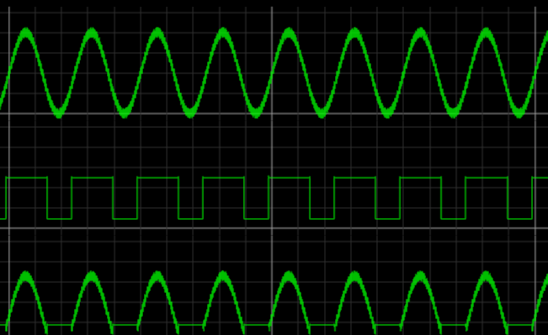
That’s a bit to process, but if you try entering the table’s input column into the simulator, you’ll see it clearly. Another way to visualize it is to look at a scope trace like the one below. The top trace is the noisy input and the middle is the output. The emitter voltage is the bottom trace. Notice how when the output is low, the bottom trace stays constant but when the output is high, it tracks the input signal. This is what changes the threshold based on the previous state. Notice how the voltage drops before it shoots back up to the off level. Then it drops suddenly to start the next high cycle.
One More Time
The Art of Electronics has a similar Schmitt trigger that uses a direct connection between the two transistors and doesn’t have an explicit voltage divider on Q2. I’ve included it along with the other two circuits in one simulation for you to experiment with.
We’ve talked about Schmitt triggers with opamps before, but there’s something satisfying about doing it with a few components. If you want a practical application, Schmitts are often in clocks that read the AC power line frequency, although you sometimes see a zero-crossing detector doing the same duty.


Big shout out to Paul Falstad and Iain Sharp! I love their simulator! Really helps with explaining to non electrical people.
Hear hear. Love using it to play around with stuff I’m trying understand in real time, and super nice that you can share links to what you’ve built in simulation.
Why are all the links tinyurls? Very user-unfriendly.
Storing the circuit “in a link” is handy, but the URL is very long which is problematic in some cases. By making it a tiny URL it is much easier to pass along the URL to an entire circuit.
Well done! This is the kind of stuff the next generation needs to learn. More like it, please!
Al,
Nice article, but no mention of Otto Schmitt? https://en.wikipedia.org/wiki/Otto_Schmitt
Just saying… I was poking around in a Minneapolis junk store and found a bunch of DEC manuals. Name on the inside cover was Dr. Schmitt’s, so I bought them all. Sometimes nice to tie to the technology to the inventor.
Cheers!