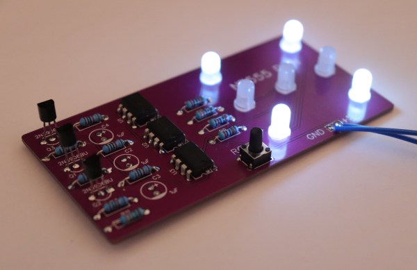
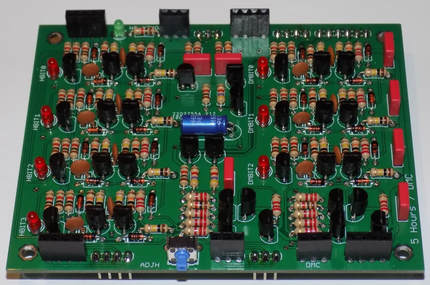
It has become a bit of a running joke in the Hackaday community to suggest that a project could or should have been done with a 555 timer. [Tim] has rather taken this to heart with his latest Electronic Dice project, which uses three of the venerable devices.
If three seems like a lot of 555s to make an electronic die, then it may be worth considering that the last time we shared his project he was using 22 of them! Since then, [Tim] has been busy optimising his design, whilst keeping within the constraints of an old-school through-hole soldering kit.
Maybe the most surprising thing about this project is the purpose to which the NE555 devices are pressed. Rather than using them for their famous oscillation properties, they are in actual fact just being used as Schmitt Triggers to clean up the three-phase ring oscillator that is constructed from discrete transistors and passives.
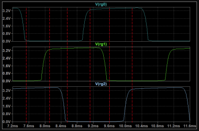
Simulation trace of the three-phase ring oscillator before Scmitt Trigger stages
The ring oscillator cleverly produces three phase-shifted square waves such that a binary combination of the three phases offers six unique states. Six being the perfect number for a dice throw, all that then remains is to figure out which LEDs need to be switched on in which state and wire them up accordingly.
To “roll” the dice, a push-button powers up the oscillator, and stops it again when it is released, displaying the random end-state on the LEDs.
It can be fun to see what can be done using old technology, and educational to try to optimise a design down to the fewest parts possible.
[Tim]’s earlier project is here if you want to see how the design has evolved. The documentation on both of these iterations is excellent and well worth a read.
In the fantasy world of schematic diagrams, wires have no resistance and square waves have infinitely sharp rise times. The real world, of course, is much crueler. There are many things you can use to help tame the wild analog world into the digital realm. Switches need debouncing, signals need limiting, and you might even need a filter. One of the basic elements you might use is a Schmitt trigger. In
In this installment of Circuit VR, I’m looking inside practical circuits by building Schmitt triggers in the Falstad circuit simulator. You can click the links and get to a live simulation of the circuit so you can do your own experiments and virtual measurements.
Why Schmitt Triggers?
You usually use a Schmitt trigger to convert a noisy signal into a clean square digital logic level. Any sort of logic gate has a threshold. For a 5V part, the threshold might be that anything under 2.5V is a zero and at 2.5V or above, the signal counts as a one. Some logic families define other thresholds and may have areas where the signal is undefined, possibly causing unpredictable outputs.
There are myriad problems with the threshold, of course. Two parts might not have exactly the same threshold. The threshold might vary a bit for temperature or other factors. For parts with no forbidden zone, what happens if the voltage is right at the edge of the threshold?
When you’ve got time on your hands, doing something the hard way can be therapeutic. Not that the present situation and the abundance of free time that many are experiencing has anything to do with [Leo Fernekes] all-transistor digital clock build, which he started a year ago with his students. But if you’ve got time to burn, this might be a good way to do it.
[Leo] says one of his design goals with this clock was to do it with the technology commercially available in 1960, which means relying completely on discrete components. And he and his students managed to do just that, with the exception of the seven-segment displays, which were built from the LED filaments from some modern light bulbs. Everything else, though, is as old school as it gets, and really underscores all the complexity that gets abstracted away from timekeeping with modern chips. The video below covers each module in detail, from the Schmitt trigger that cleans up the 50-Hz line frequency to the ring counters and diode matrices used to drive the display. We found the analog stair step dividers used to bring the line frequency down to a more usable pulse train particularly interesting. That clever bit of engineering saved 10 transistors over what would be required for traditional flip-flop dividers.
There’s a lot to learn from this design, and the execution is great too – we’re suckers for Manhattan-style builds, of course. Hats off to [Leo] and his lucky students on a great build.
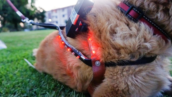
[javier.borquez] likes to take his dog to the hang out at the dog park around dusk. But once the sun goes down and [Rusio]’s off the leash, running amok with the other dogs, it’s almost impossible to keep track of him.
Sure, there are probably glow-in-the-dark or lighted collars out there, but if you go commercial, chances are good that someone else’s dog will be wearing the same thing. Besides, what’s the fun in buying something that you can do a better job making yourself? With this dog distance indicator harness, you don’t even have to program anything. Instead, it uses a cheap pair of modified walkie talkies to show green LEDs on the harness while the dog is in range, and red when it isn’t.
Although [javier]’s pupper is the best pupper yes he is, [Rusio] can’t be expected to hold down the button and bark his location. His walkie talkie uses a 555-based frequency generator and a glued-down button to speak at 1 kHz.
Over in [javier]’s walkie, there’s a resistor in place of the speaker to keep the talkie parts working. There’s also a half-wave bridge rectifier that charges a capacitor when [Rusio] is within range, and a resistor that drains it when he’s outside the 6-8 meter range. The rectifier’s output goes to a second 555 set up as a Schmitt trigger, which tells a transistor to turn the red LEDs on instead.
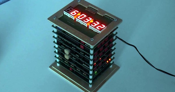
A couple years back we covered a very impressive transistor logic clock which was laid out so an observer could watch all of the counters doing their thing, complete with gratuitous blinkenlights. It had 777 transistors on 41 perfboards, and exactly zero crystals: the clock signal was extracted from the mains frequency of 50 Hz. It was obviously a labor of love and certainly looked impressive, but it wasn’t exactly the most practical timepiece we’d ever seen.
Creator [B Brett] recently wrote in to share news that the second version of his transistor logic clock has been completed, and we can confidently say it’s a triumph. He’s dropped the 41 perfboards in favor of 9 professionally fabricated PCBs, which this time around are stacked vertically to make it a bit more desktop friendly. The end goal of a transistor logic clock that you can take apart to study is the same, but this “MkII” as he calls it is a far more refined version of the concept.
In addition to using fewer boards, the new MkII design cuts the logic down to only 283 transistors. This is thanks in part to the fact that he allowed himself the luxury of including an oscillator this time. The clock uses a standard watch crystal at 32.768 KHz, the output of which is converted into a square wave through a Schmitt trigger. This is then fed into a divider higher up the stack which uses flip flops to produce 1Hz and 2Hz signals for use throughout the rest of the clock.
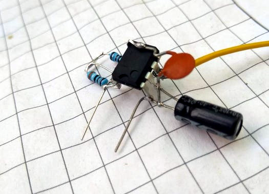
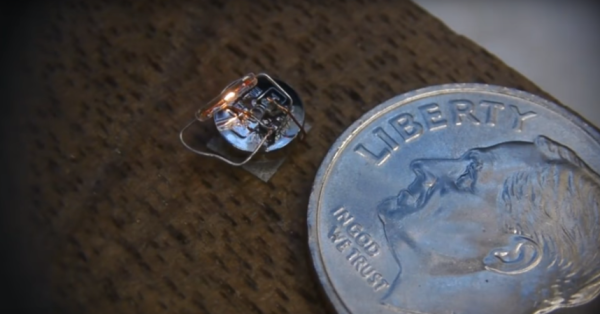
We’re going to go out on a limb here and declare this minuscule incandescent light flasher the smallest such circuit in the world. After all, when you need a microscope to see it work, you’ve probably succeeded in making the world’s smallest something.
Even if it’s not record breaking, [Ben Krasnow]’s diminutive entry in the 2017 Flashing Light Contest, which we recently covered, is still pretty keen. For those not familiar with the contest, it’s an informal challenge to build something that electrically switches an incandescent light on and off in the most interesting way possible for the chance to win £200. [Ben] says he’ll donate the prize money to a STEM charity if he wins, and we’d say he has a good chance with this flea-sized entry.
The incandescent lamp he chose is a specialty item for model makers and scale railroad enthusiasts; we’d heard of “grain of wheat” bulbs before, but this thing is ridiculous. The bulb makes the 4.6 mm diameter SR416 hearing aid battery that powers the flasher look enormous. The driver is a clever Schmitt trigger inverter with a tiny RC network to flash the bulb at about 1 Hz. The video below shows the flasher working and details the development and the build, which featured spot welding to the battery. [Ben] has even spec’d precisely how many Joules of energy will rupture the thing steel cases on these cells — we suspect involuntarily through trial and error.
[Ben]’s entry in the contest is now our favorite, and not just because he’s been a great friend to Hackaday with such classic hacks as watching a phonograph needle with an electron microscope and a homebrew CT scanner. This circuit is genuinely fascinating, and we hope it inspires you to try to top it. There’s a little less than a month left in the contest, so get to it.
There is an old saying: “In theory, theory and practice are the same. In practice, they are not.” We spend our time drawing on paper or a computer screen, perfect wires, ideal resistors, and flawless waveforms. Alas, the real world is not so kind. Components have all kinds of nasty parasitic effects and no signal looks like it does in the pages of a text book.
Consider the following problem. You have a sine wave input coming in that varies between 0 V and 5 V. You want to convert it to a square wave that is high when the sine wave is over 2.5 V. Simple, right? You could use a CMOS logic gate or a comparator. In theory…
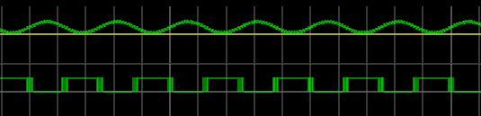
The problem is, the sine wave isn’t perfect. And the other components will have little issues. If you’ve ever tried this in real life, you’ll find that when the sine wave is right at the 2.5 V mark the output will probably swing back and forth before it settles down. This is exacerbated by any noise or stretching in the sine wave. You will wind up with something like this:
Notice how the edges of the square wave are a bit fat? That’s the output switching rapidly back and forth right at the comparator’s threshold.
Hysteresis
The answer is to not set the threshold at 2.5 V, or any other single value. Instead, impose a range outside of which it will switch, switching low when it leaves the low end of the range, and high when it exceeds the high end. That is, you want to introduce hysteresis. For example, if the 0 to 1 shift occurs at, say, 1.9 V and the 1 to 0 switch is at 0.5 V, you’ll get a clean signal because once a 0 to 1 transition happens at 1.9 V, it’ll take a lot of noise to flip it all the way back below 0.5 V.
You see the same effect in temperature controllers, for example. If you have a heater and a thermal probe, you can’t easily set a 100 degree set point by turning the heater off right away when you reach 100 and then back on again at 99.9999. You will usually use hysteresis in this case, too (if not something more sophisticated like a PID). You might turn the heater off at 99 degrees and back on again at 95 degrees, for example. Indeed, your thermostat at home is a prime example of a system with hysteresis — it has a dead-band of a few degrees so that it’s not constantly turning itself on and off.
Schmitt Triggers and How to Get One
A Schmitt Trigger is basically a comparator with hysteresis. Instead of comparing the incoming voltage with VCC / 2, as a simple comparator would, it incorporates a dead band to ensure that logic-level transitions occur only once even in the presence of a noisy input signal.
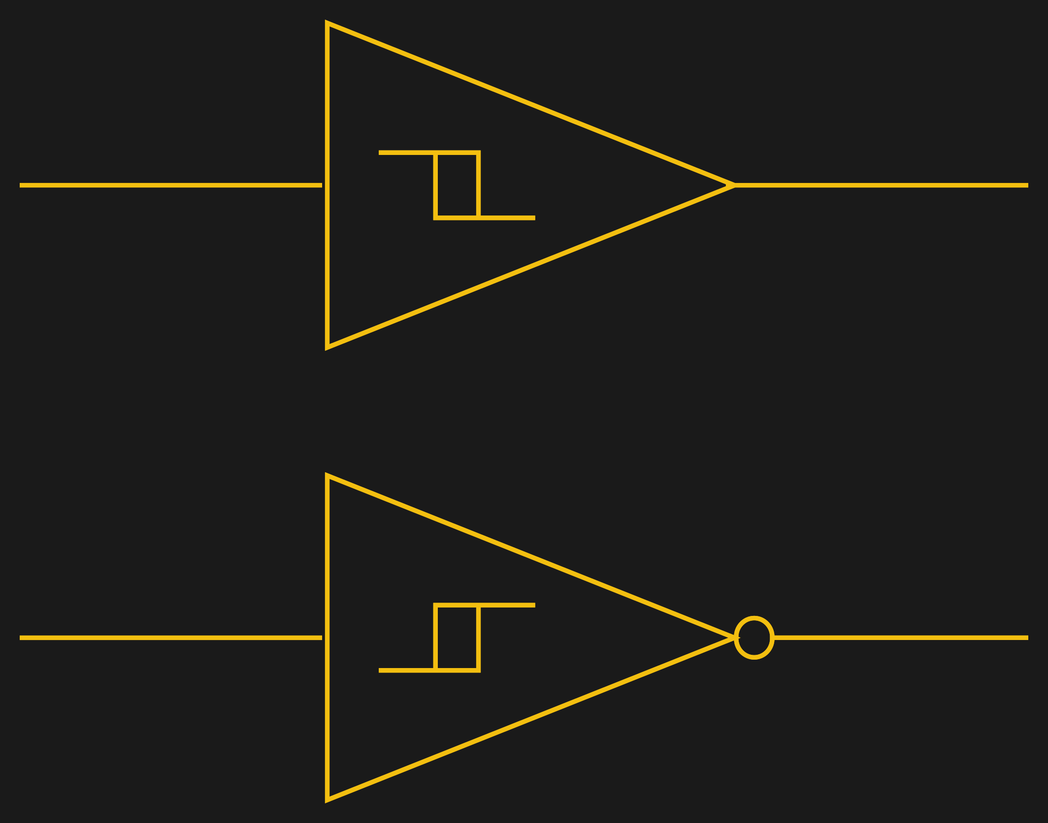
Assuming you want a Schmitt trigger in a circuit, you have plenty of options. There are ICs like the 74HC14 that include six (inverting) Schmitt triggers. On a schematic, each gate is represented by one of the symbols to the right; the little mark in the box is the hysteresis curve, and the little bubble on the output indicates logical negation when it’s an inverter.
You can also make them yourself out of transistors or even a 555 chip. But the easiest way by far is to introduce some feedback into a plain op amp comparator circuit.
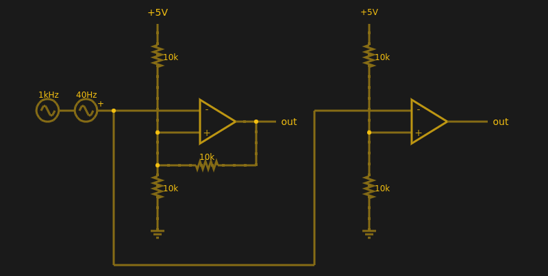
Below are two op amps, one with some positive feedback to make it act like a Schmitt trigger. The other is just a plain comparator. You can simulate the design online.
If you haven’t analyzed many op amp circuits, this is a good one to try. First, imagine an op amp has the following characteristics:
The inputs are totally open.
The output will do whatever it takes to make the inputs voltages the same, up to the power supply rails.
Neither of these are totally true (theory vs. practice, again), but they are close enough.
The comparator on the right doesn’t load the inputs at all, because the input pins are open circuit, and the output swings to either 0 V or 5 V to try, unsuccessfully, to make the inputs match. It can’t change the inputs because there is no feedback, but it does make a fine comparator. The voltage divider on the + pin provides a reference voltage. Anything under that voltage will swing the output one way. Over the voltage will swing it the other way. If the voltages are exactly the same? That’s one reason you need hysteresis.
The comparator’s voltage divider sets the + pin to 1/2 the supply voltage (2.5 V). Look at the Schmitt trigger (on top). If the output goes between 0 V and 5 V, then the voltage divider winds up with either the top or bottom resistor in parallel with the 10K feedback resistor. That is, the feedback resistor will either be connected to 5 V or ground.
Of course, two 10K resistors in parallel will effectively be 5K. So the voltage divider will be either 5000/15000 (1/3) or 10000/15000 (2/3) depending on the state of the output. Given the 5 V input to the divider, the threshold will be 5/3 V (1.67 V) or 10/3 V (3.33 V). You can, of course, alter the thresholds by changing the resistor values appropriately.
Practical Applications
Schmitt triggers are used in many applications where a noisy signal requires squaring up. Noisy sensors, like an IR sensor for example, can benefit from a Schmitt trigger. In addition, the defined output for all voltage ranges makes it handy when you are trying to “read” a capacitor being charged and discharged. You can use that principle to make a Schmitt trigger into an oscillator or use it to debounce switches.
If you want to see a practical project that uses a 555-based Schmitt, check out this light sensor. The Schmitt trigger is just one tool used to fight the imprecision of the real world and real components. Indeed, they’re nearly essential any time you want to directly convert an analog signal into a one-bit, on-off digital representation.