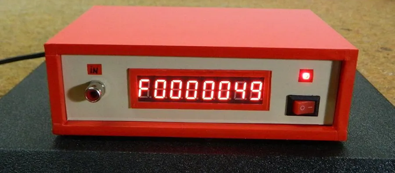
We were struck by how attractive [mircemk’s] Arduino-based frequency counter looks. It also is a reasonably simple build. It can count up to 6.5 MHz which isn’t that much, but there’s a lot you can do even with that limitation.
The LED display is decidedly retro. Inside a very modern Arduino Nano does most of the work. There is a simple shaping circuit to improve the response to irregular-shaped input waveforms. We’d have probably used a single op-amp as a zero-crossing detector. Admittedly, that’s a bit more complex, but not much more and it should give better results.
There was a time when a display like this would have meant some time wiring, but with cheap Max 7219 board available, it is easy to add a display like this to nearly anything. An SPI interface takes a few wires and all the hard work and wiring is done on the module.
The code is short and sweet. There are fewer than 30 lines of code thanks to LED drivers and a frequency counter component borrowed from GitHub.
If you add a bit more hardware, 100 MHz is an easy target. There are at least three methods commonly used to measure frequency. Each has its pros and cons.


Lacking schematic, but at least a bit of HP and afterwards LP filtering along with limited input protection (not that many of his targeted readers are likely to identify those components).
Well, it isn’t a proper schematic, but the pictorial of the circuit is a kind of schematic. You could certainly draw a proper schematic from it.
I wrote lacking, not incorrect. Many components are missing values. The filters’ cut-off frequencies kind of depend on both values being correct…
He needs to add one of these, “Arduino 24 GHz Frequency Counter”. It’s not really a 24 GHz Arduino counter, but rather a clever prescaler added to an Arduino counter that “maybe” works through 24 GHz:
https://www.changpuak.ch/electronics/Arduino-24_GHz_Counter.php
Skip the enclosure though, that little “Sucobox” from Huber & Suhner (Swiss) costs like $200 USD ea.
It’s up to 15GHz due to limitation of bandwidth of the first prescaler. Also I don’t think the physical construction would permit it to work reliably at that frequency. I’d say the problems might start around 3-5GHz…
Yeah you may be right, I just parroted their title. But even 15 GHz would be a nice boost over 6.5 MHz! To get that high in frequency with small signals the input is going to be bare naked though; little (if anything) in the way of protection.
[Mircemk] could push his 6.5 MHz box to ~40 MHz by addind a 74LVXXX counter as a prescaler (SN74LV8154 maybe?)
A 74196 would go up to 50MHz, thiugh it was seen in frequency counters as the first counter.
I would add a filter over the LED display to make it look better. Also 6,5MHz? A bit too little, but that’s the problem with the Atmega328 – it would take a Schmitt trigger and frequency divider/prescaler to increase the range. Just for fun check out this old frequency counter that goes to 50MHz because PIC micros include prescalers on their timers/counters:
https://www.qsl.net/dl4yhf/freq_counter/freq_counter.html
“We were struck by how attractive [mircemk’s] Arduino-based frequency counter looks.”
Attractive? Well, maybe more attractive than MDF or cardboard…
Seriously? Dude! I think it’s cool.
I’m not sure why anyone would actually want to mimic this, given the extremely low upper frequency limit and total lack of a even half-respectable oscillator… Can we say error? Lmao
There are thousands of better frequency counter projects out there for all of you makers to mimic.
OK. So this isn’t your thing. . . but many of us are into retro shortwave and am radio. It’s a fascinating world.