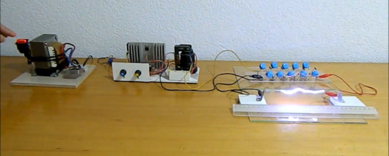
There’s something satisfying about creating high voltages. Sure, there are practical uses like neon signs or doing certain experiments, but be honest — you really just want to see some giant arcs lighting up your dark mad scientist lair. [Mircemk] has just the prescription for what ails you. Using a two-stage approach, he shows a simple setup that generates about 110KV from a pretty tame 15V supply.
From the 15V, there is a stage that uses a flyback transformer and a switch to generate a reasonably high voltage. The final stage is a Cockroft-Walton voltage multiplier that can produce quite a bit of voltage. You can see the impressive arcs in the video below.
The multiplier circuit found fame with experiments by Cockroft and Walton, obviously, but was actually originated in the early 1900s with a physicist named Greinacher. The circuit uses diodes as switches and charges a bank of capacitors in parallel. The discharge, however, puts the capacitors in series. Neglecting losses and loads, the output voltage is equal to the peak-to-peak input voltage times the number of stages present. Real-world considerations mean you won’t quite get that voltage out of it, but it can still provide a potent punch. Click through the break for a video of the circuit in action!
There are lots of ways to generate high voltages. Just be careful making measurements.


What voltage are rated those caps ? 110kV or more ? I doubt so.
Each cap doesn’t have to be rated for the full output voltage since they will each only see a fraction of that voltage across them (the voltage multiplier consists of stages). Similar in the way that stacking caps in series in a dc system will have each cap charged to a fraction of the total voltage across the full series string.
If I recall, no single cap will see more than 2x the input voltage.
Yeah, that’s correct. In a Cockroft-Walton multiplier, each cap sees no more than double the input voltage. Given a decent safety margin the 30kV caps used should be suitable if the output from the flyback is no more than 10kV.
Electic arcs are cool, and an excellent source of UV radiation :) Keep your retinas safe, kids!
That, and Ozone (poisonous), and broad-band radio frequency noise. Really awesome though!
Ozone is not poisonous it is a mild irritant. It will also kill bacteria and viruses
…….and it sods up any radio reception! Your neighbours will love you. I would assume t hat also Mobiles would be affected.
I wonder if this could this be modified to transmit a radio signal? (i.e. spark gap transmitter)
It is a spark gap transmitter.
Yes and no, right? It’s a spark gap but it’s only “transmitting” radio interference. I don’t know how they work and I need to read more. I suspect that it would have a fairly high wattage and maybe they are too primitive to tune to a specific frequency. So it might not even be legal to use with my dinky technician license.
Ah jeez, now I understand. What I was thinking wouldn’t work for so many reasons. They’re too primitive. And it’s not legal to use damped waves to transmit anything, and furthermore they can’t transmit sound.
Very cool project, hv is fun. I built something like this to try and revive a night vision monocular tube. It used a voltage doubler circuit, voltage was high enough to kill the multi meter and make some nice arcs. Monocular tube lit up but too much voltage may have killed the phosphorous…. all was white. https://en.wikipedia.org/wiki/Cockcroft%E2%80%93Walton_generator
Electro Boom did a video on this same thing a couple weeks ago
https://youtu.be/dje7uhyW23o
it’s been on a lot of youtube videos – I made a 12 stage one off of 2xAA battery EL wire output. It was about 15kv.
Elrctro Boom video is a “Marx generator”
Why step down from 220 (or 110) volts and then step up? Wouldn’t you need less capacitor/diode stages if you went straight from mains?
Couple reasons – a flyback transformer operates at a high frequency (several 10s of KHz, possibly higher). This allows much smoother output. Running from mains directly would result in a relatively low frequency of pulses from the output. Second is safety – the mains in the US can deliver at least 10 amps at 120 V (1200 watts), and much higher in other parts of the world. A high voltage source connected directly across the mains would not be intrinsically current-limited, and could deliver a [very] fatal shock. The low-voltage transformer provides galvanic isolation, so the high-voltage side is not directly connected to the mains.
First, for isolation from the mains.
Second, you don’t want to do this at line frequency (50 or 60Hz.)
You need large capacitors at low frequencies – and those are expensive at high voltage.
You convert to DC, generate a high frequency signal, step it up with a transformer, then use the multiplier to go from high voltage, high frequency to much higher voltage DC.
An 8-min video with a 2-min ad embedded in the middle?
ABORT
youtube-dl is your friend.
Why does the image of the arc appear randomly displaced from the actual arc? I assume it’s somehow the camera’s doing, but that doesn’t explain anything…
I asked to myself the same question. Is it a video glitch ? Is it optical / EMC related ?
Probably the camera framerate being just about the same as the arc frequency, combined with rolling shutter.
This used to be common design to drive paint gun for electrostatic painting equipment.