USB-C Power Delivery 3.0 (PD3.0) introduces a new Programmable Power Supply (PPS) mode, which allows a device to negotiate any supply of 3.3-21 V in 20 mV steps, and up to 5 A of current in 50 mA steps. To make use of this new standard, [Ryan Ma] create the PD Micro, an Arduino-compatible development board, and a self-contained software library to allow easy integration of PD3.0 and the older PD2.0 into projects.
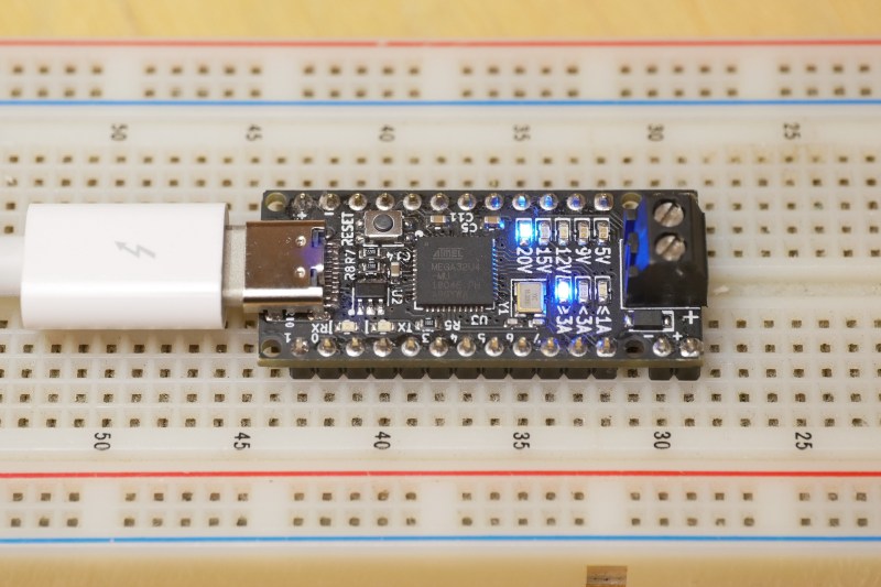
The dev board is built around an ATMega32U4 microcontroller and FUSB302 USB-C PHY. The four-layer PCB is densely packed on both sides to fit in the Arduino Pro Micro Form factor. The board can deliver up to 100W (20 V at 5 A) from an appropriate power source and shows visual feedback on the PD status through a set of LEDs.
The primary goal of the project is actually in the software. [Ryan] found that existing software libraries for PD take up a lot of memory, and are difficult to integrate into small projects. Working from the PD specifications and PD PHY chip data sheet, he created a lighter weight and self-contained software library which consumes less than 8 K of flash and 1 K of RAM. This is less than half the Flash and RAM available on the ATmega32U4.
[Ryan] is running a Crowd Supply campaign (video after the break) to get some of these powerful boards out in the wild, and has released all the source code and schematics on GitHub. The PCB design files will be released during the last week of the campaign, around 25 January 2021.
USB-C and power delivery are not simple standards, but the ability to add a high-speed data interface and a programmable power supply into almost any project has real potential.


Arduino based soldering iron?
Original Arduinos are far too underpowered to run a device with a single bit of output (heat on, heat off) we need 32 bit RISC chips at a couple hundred Mhz nowadays https://hackaday.com/2021/01/05/review-pine64-pinecil-soldering-iron/ :-D
How can it possibly know when to turn on the heating element without IoT and cloud computing?
Original ones maybe but this can deliver up to 100W (20 V at 5 A).
@RW ver 0.0.1 said: “Original Arduinos are far too underpowered to run a device with a single bit of output (heat on, heat off) we need 32 bit RISC chips at a couple hundred Mhz nowadays”
Nonsense. An original Arduino is more than enough to run a PID controller for voltage, current, temperature, whatever, in terms of Human usability. In-fact you don’t even need an Arduino in the first place if you make your controller analog based. Where the micro-controller helps is in an application where the target is rather dynamic like a soldering iron that you want to auto-turn-off when it is not picked up, and auto-turn-on when it is picked up. That’s harder to do with a strictly analog controller.
you have located the joke
Like the kids say, “r/whoosh.”
Excellent
Woosh
RW ver 0.01 is wasting many many thousands of CPU cycles by using a modern computer to type their comments when a 1 Mhz Apple II will do the job just as well. You should be ashamed of your waste.
SHould bring back the old Pentium 4. Need the computing power for the PID as well as heating. :P
Use a 66 Mhz original Pentium for the heating.
16W Max, 13W typical… and we used to think that was hot.
Then, the notorious K6-233 APR, 30.2W Max, 18.2W Typ… and we used to think that was hot.
Then, the 1st Coppermines that struggled to get 1.13Ghz… 35.5W Max, 23W Typ… and we used to think that was hot.
Fastest Willamette P4 at 2.0Ghz… 95.7W Max, 71.8W Typ… and we used to think that was hot.
Prescott P4 571 (3.8GHz – 1MB)… “115” W TDP…. but we know it needed a 119A max at 1.55V and Intel thought nobody could do math and realise that the sucker pulls 184.45W Max and needs to get rid of it somehow… and we used to think that was hot.
Enter Core i9 10900k
.. and by the way … https://www.electronicsforu.com/electronics-projects/variable-power-supply-with-digital-control
Use the max of four parallel ports for an interface, each with a well chosen resistor ladder. Have them control a 555 to output a pwm signal to a heavy duty transistor. 32 bit precision power supply that runs under DOS.
36 bit, if you also use the strobes too.
And 32 bit feedback with the right isolation.
You don’t need 4 parallel ports. One would do. Just have 4 D f/f hooked up to the same data bus. Use the handshake lines to individually clock the data to each latch. Alternatively bit-bang SPI to a chain of 74xx595.
It gets very trick to get more than 6 bits with resistor ladder with discretes. :P Even for precision laser trimmed network, it can get tricky and expensive for very high res. That’s why they use single bit delta-sigma D/A converters.
I may have spoken too soon.
https://hackaday.io/project/176844-trollduino-v10
That Trollduino looks kinda cool!
I’d really like to have a slim universal PSU device to replace many different clunky PSU bricks for other older PC peripherals like paper scanners, laser printers, cameras with external PSU options, etcetera. I have plenty of such peripherals that are still used, but not very often and very rarily at the same time. Ideally we could put all the different old PSU bricks in a box on the attic and replace them with (1) one extruding/hol pin adapter per peripheral device (slim and cheap enough to leave in the hardware permanently) and (2) the universal PSU device. It seems we’re moving towards powering laptops, phones and more with USB anyway, so expanding that backwards to older hardware would be great.
I think they’re a bit expensive at $28. You can find similar modules on aliexpress for a couple of bucks :)
“The primary goal of the project is actually in the software. “
Too much CPU’s power and not enough cooper in wires as for PSU project…
‘cooper’?
You called?
Designer of the PD Buddy Sink here. Those cheap modules on AliExpress don’t provide any way to switch off the load when the correct power isn’t available, or at other times when required by the PD spec (e.g. voltage transitions). I don’t feel comfortable knowingly doing things wrong with amounts of power that can definitely start fires.
“negotiate any supply of 3.3-21 V in 20 mV steps” where did you get that at? Nothing on his page says this.
Two out of three of the project links state that. The only one that doesn’t is the Crowd Supply link.
The CSL is the most important one. The others are the USB-C spec. This does not mean his does it
Isn’t the whole point of the project a device that negotiates the USB spec?
The device itself doesn’t actually control if the power supply actually supplies the requested power.
So the device is capable of everything it said, but it must be mated to a power supply that complies.
Yes it does, in fact there’s a section in the README that describes in great detail how the device supports programmable power supplies.
No one else has asked it yet, but I can’t be the only one thinking it:
Why does it take so much work to use USB PD?
Granted, most devices that will need to use its higher power capability are things like a laptop, but it’s not like it’s a lot of complicated coordination is required to communicate “I can handle 20V max, need at least 1 A and 30W.”
Think back to simpler times, when an entire automation system could run on modbus. For the end devices, you barely need more than a few registers—forget 1k of RAM and 8k of program memory.
It just seems like making it harder than it needs to be. If anyone has insight as to why it’s so complicated, please explain.
Because you’re conveniently ignoring everything except the absolute simplest case – one already powered device that knows it’s a source, and one unpowered device that knows it’s a sink. What happens with a laptop that sometimes has to source and sometimes has to sink? What happens if two such dual-role devices are connected together? What happens when both sides already have power? What happens when you need a device to *normally* be a source, but be a sink in certain specific circumstances? Or the other way around? What happens when you have a battery so you’re normally powered but the battery is dead?
PD is complicated because it needs to do a lot.
“PD is complicated because it needs to do a lot.”
Have you actually developed some software for USB PD?
All the cases you mentioned were covered is USB OTG and QC standards using super simple logic. Those were not perfect but did the job.
USB PD is extremely complicated. I developed simple USB PD decoy using STM32G4 and its integrated UCPD peripheral. It was a nightmare. As in usual ST’s style the software is a mess. The PD library itself is a binary blob with poor documentation and included examples are broken. From my point of view USB PD stack is more complicated than basic USB2 HS device stack.
Hey I’m working with the STM32G4 and am finding it equally frustrating to get it working. Would you be willing to share your learnings or code?
It does not necessarily take a lot of work. Cypress CYPD3177 is a USB PD chip that only needs 2 resistor dividers to negotiate standard PD voltage and current levels ( without the 20 mV/ 50 mA).
https://hackaday.io/project/168762-usb-c-power-delivery-sink-cypd3177
Hum i don’t know PD so i am probably talking out of my excretion tube but is this project can fit on an attiny with vusb that would be 1.65USD vs (0.35+6x.0.02+2×0.05) ~0.7 USD USD (attiny+2zeners+4resistors+2capacitors) If you have simple power requirements and have the PCB real estate that could be nice…
Nice idea, but it assumes I already have a compatible USB power supply. Build a complete programmable bench power supply, and I’ll open my wallet.
Make sure it’s 120V/240V compatible. Might want to use IEC socket, and sell the maiins power cable seperately.
Yes it assumes so because most people already have such USB power supply, or will tend to have more and more in the future when USB charging of laptops become more common.
If you want a programmable bench power supply, there are lots of them already available, this project has other goals.
I disagree about the mains compatibility. The beauty of this, or something like this, for me is that I could develop, prototype and debug on the move. With a meaty USBC power bank, my TS80P, Analog Discovery, Digital Discovery, and laptop, that’s everything to allow me to work pretty much anywhere, without needing any mains.
There are lots of mains powered solutions, but very few portable, adjustable, PSUs that supply more than a few tens to hundreds of milliamps.
I like this.
This isn’t for people who want to buy a power supply from scratch. It’s for those who already have or have use for PD3.0 PPS chargers to use and play around with.
I just want a smart USB charging gizmo that can plug between any USB port and device, test the port for how much power can be drawn, how much power the device can draw, and arrange things to draw the most power that can safely be done. I put a 3 amp USB 2 charger in a truck but the silly thing doesn’t even have the data lines shorted in its two ports (which are encased in soft molded plastic) so devices only see it as a standard USB 2.0 port capable of a maximum of 500 milliamps.
I’ve never gotten around to making little adapters with the data lines shorted together on the output side to make devices see it as a power port capable of up to 1 amp. I should get a couple of Type A port connectors and redo the ports installed in the dash so the data lines will be shorted, but it’d really be nice to have some smart charge circuitry able to sense Apple, Samsung and other ways of detecting compatible, higher power charge capability.
PD Micro sure looks like a neat little board for USB PD. Breaking out all the I/O pins and using a switching DC-DC converter are great additions too! Once upon a time I started to work on a board called “PD Buddy Dev” that would have been similar, but life got in the way and it never happened. I guess people who aren’t me probably like using Arduino more than ChibiOS anyway, hehe.
I like ChibiOS way more than Arduino!
A pity that the licensing scheme has changed and it is no longer free for commercial use. I would love to use it instead of crappy FreeRTOS but it’s hard to justify the cost for new product and FreeRTOS is still more popular.
Anyway, I think ChibiOS is spectacularly good!
Why? Seriously why screwing around with the USB voltages at the first place? 5V and 12V I can understand but 20V??? For what the hell do you need 20V on USB. The next step would be poe with 48V but we are far from it. I don’t like these new standards at all.
Up to 20v on USB-C is usually used for charging laptops. Why does that bother you?
You will definitelly not like USB PD Extended Power Range (EPR) then :D.
Up to 48V at 5A.
https://heise.cloudimg.io/v7/_www-heise-de_/imgs/18/3/1/1/1/1/1/1/usb-pd-epr-ranges-b097dc193df7158b.png?q=85&width=1393
New powerful laptops need powerful power sources.
We do not want more then 5A over thin USB wires so we need to increase the voltage.
Complimentary to the (very interesting) project – these devices exist already for about 12 months as miniature “Lab Supplies”: 0 – 30V, 0 – 2A
I got mine from https://lab401.com/products/pocket-usb-power-supply but there are variations all over AliExpress
That device you linked looked interesting – to start with. Searching for any reasonable info about it draws a big blank. Reading some comments on a previous HaD article (https://hackaday.com/2020/10/19/bench-supplies-get-smaller-thanks-to-usb-c/) lends some clues…. I am no longer considering adding one to my toolkit.
Poor UI, poor over-current response, poor regulation, high noise…. the only thing going for it is its’ size.
For the older USB types, at some point there were devices made that would allow charging at max rates, but disconnect any possibility to use the data lines; to make charging at public locations safe. This sounds like it is halfway there, does such a device already exist for USB-C?
So how do you configure this board to deliver 20V @ 5A ? 100W surely cannot be coming in through the USB-C connector.
That’s the max rating of USB-C 20V, 5A. There are even some designs that exceed that (dell, 130W on usb-c).
I think I’d rather have dip switches to select voltage tho…
An interesting project. For me, support for Qualcom Quick charge 3.0 is still missing.
Or an upgrade to QC 4.0/4+, which would make many more USB power supplies compatible.
Is there any newer version of this utalizing an esp32 or something else supporting wifi or Bluetooth? Would be nice to be able to use this as a lab bench power supply which can be controlled by a smartphone.
Does this interface nicely to a Linux OS?