
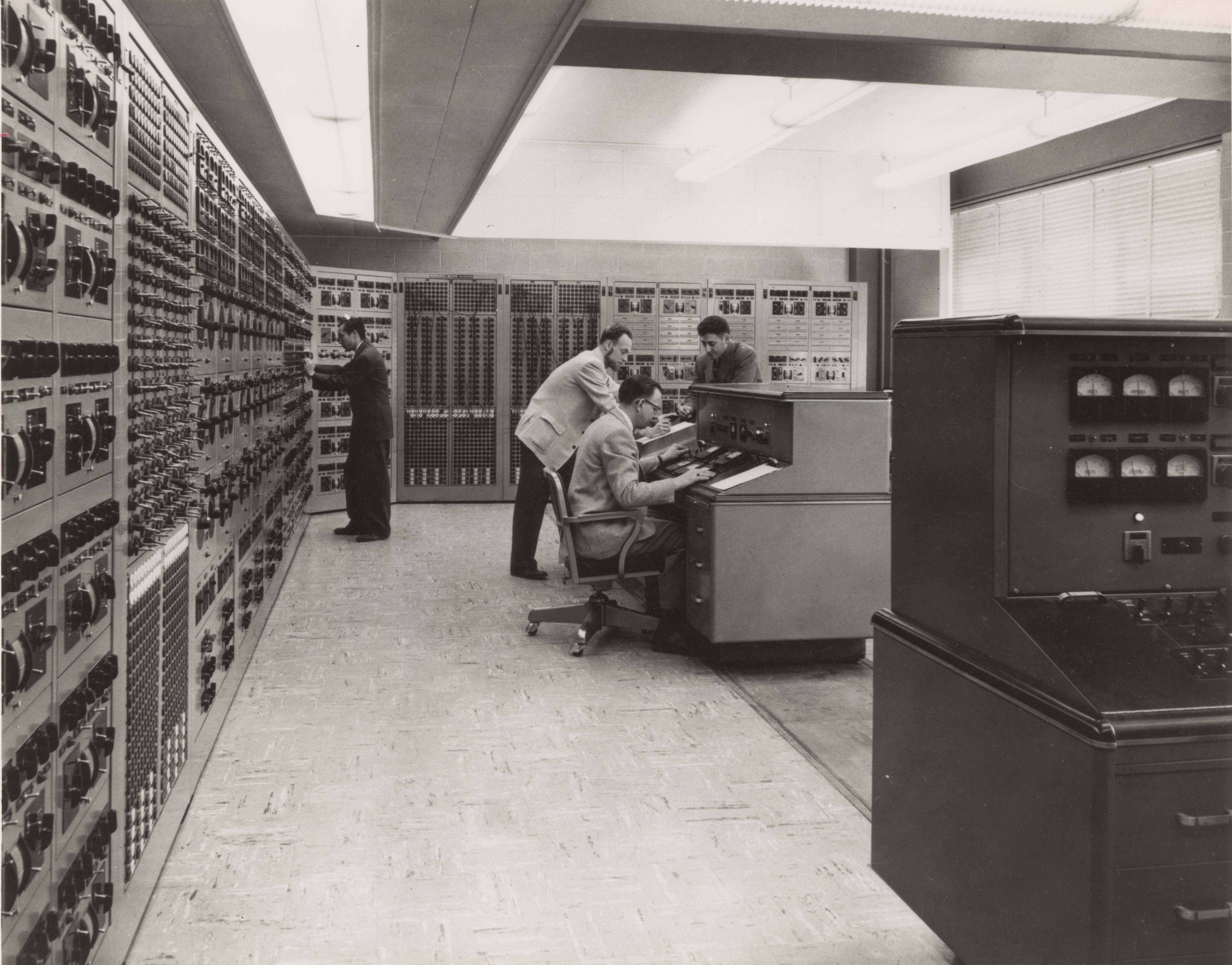
How do you rapidly record the output from your three million dollar analog computer in the 1940s when the results are only available on analog meters? The team responsible for the Westinghouse 1947 AC Network Calculator at Georgia Tech was faced with just this problem and came up with a nifty solution — hack the control panel and wire in a special-purpose drafting table.
What Is It?
 What is this beast of a computer? Machines of this type were developed during and after World War 2, and strictly speaking, belong in the category of scale models rather than true computers. Although these machines were very flexible, they were primarily designed to simulate power distribution grids. There is a lot of theory under the hood, but basically a real world, multi-phase distribution system would be scaled to single-phase at 400 Hz for modeling.
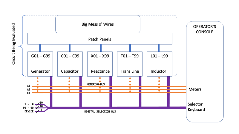
The engineers would “program” the machine by connecting together the appropriate circuit elements (like capacitors, inductors, transmission lines, generators, etc.) on big patch panels. Thus programmed, a 10 kW motor-generator located in the basement would be started up and the simulation was underway.
Part Time Job
Back in the early 1980s, my first job in college was to get one of these machines up and running. It had been purchased by Georgia Power and donated to Georgia Tech back in 1947, where it had seen more or less continuous service for several decades. It had then been used as a teaching aid for some time, and moved to a couple of locations. By the time of my involvement, it was unused and in a state of disrepair.
Surprisingly, it wasn’t that difficult to fix. The patch panels’ wiring needed replacement, as the insulation was brittle and cracked. Decades of crud was removed from the switches and contacts in all of the circuit elements. For several semesters, this quiet room in the basement was my refuge when I needed silence to study and read, occasionally entertaining myself by firing it up to solve random AC network problems from my textbook.
Operation
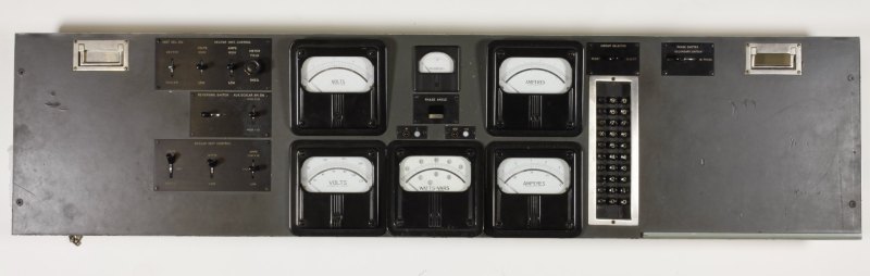
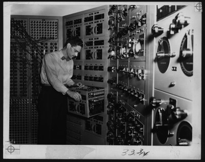
Once the motor generator set spun up to frequency and stabilized, you could monitor the simulated network by connecting the metering circuits in the operator’s console to any of the circuit elements. You did this by pressing the reference designator into a keyboard that looked like an old-fashioned mechanical adding machine (it probably was). Almost instantly, the element’s current, voltage and power would be displayed. These quantities were complex, so both magnitude and phase were presented on the meters.
The operators would obtained the simulation results by stepping through all the desired circuit elements. After each measurement, they would pause, record numbers in a notebook, and move on to the next element.
Interestingly, this whole process was basically a big passive circuit without any active components. Sure, there were relays for meter connections, and of course the motor-generator provided power for the voltage sources. Other than that, reading the output from the console was equivalent to having a technician carry test meters around to each circuit and probing the points by hand. There was one exception, one of the meters was driven by a small vacuum tube amplifier. But it was only used for one measurement type, I think it was VARS. Even with the amplifier turned off, the machine was completely functional and quite useful.
We Can Do Better
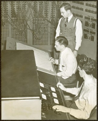
The team decided to modify the calculator so that results would be easier to record and interpret by the engineers. Their approach was to write the answers directly on the schematics, aided by the installation of a special drafting table next to the main operator’s console.
This drafting table’s top was like no other you’ve seen. It lifted up like the hood of a car, complete with supporting bracket. The table top was made primarily of metal, with a translucent material laminated on top to provide a smooth writing surface. The metal plate was perforated with small holes throughout in a regular grid pattern, accessible from the bottom. If you examined it closely, you would notice that the whole plate was connected to ground by a flexible braided strap.
Inside the table, there was a panel with a grid of hundreds of well-labeled pin-tip jacks. There was one pin-jack for each of the circuit elements — C1 to C99, L1 to L99, etc. The engineers dug into the main console keyboard and tapped into the appropriate logic signals. These were routed to new relay circuitry inside the table, and ultimately to the big panel of pin-tip jacks. Each of these circuits would be energized corresponding to the circuit element the operator engaged for metering.
There was also a big jumble of loose, single-conductor jumper wires inside the table. Each jumper wire had a pin-tip plug on one end and a small light bulb on the other. These light bulbs, T-1 3/4 midget flange base as I recall, could be gently pushed into any of the holes underneath the table, thereby grounding one side of the filament. The pin-tip plug on the jumper wire would be plugged into any desired jack on the panel, completing the circuit to the other end of the filament.
Getting output from the simulation now would require a new setup procedure. Not only did the circuit itself have to be “patched” in, but the indicator bulbs had to be connected. A schematic page was taped down on the drafting table. Then dozens of these light bulbs with jumper wires were put in place. Each bulb would be mounted in the hole underneath the corresponding element on the schematic. Then the wire would be plugged into the corresponding jack on the panel. For example, the light bulb plugged into the table underneath capacitor C16 would be plugged into the C16 tip-jack on the patch panel, and so on.
Once this rat’s nest of wires was hooked up, the table top would be closed and used like a regular drafting table. The network analyzer begins running, and one operator (at the console) would cycle through each of the various elements of interest, calling out the values from the meters. A second operator, at the drafting table right next to the console, would write the results directly onto the schematic, guided by the illuminated spot appearing under each element as it was selected by the operator. Looking back, this reminds me of a crude precursor to modern GUI SPICE simulators, where you hover your mouse or click on a circuit element to see these “metered” values.
Old Schematics
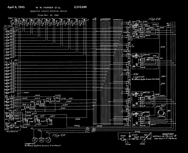
I found a schematic drawing of the meter selection circuitry from a patent filed in 1940. I found it very interesting, if only because of the different symbology and style from today’s schematics. You don’t see such a mass of relays very often these days, but if you study it briefly you can understand the gist of the circuit. It’s basically a 24-wire decimal-digit address bus, with a units and tens place. What would be the hundreds place consists of only four wires instead of ten. These are used to select the category of circuit element, such as power supply, capacitor, etc. The keypad drives the address bus, and the RESET button releases the “drivers”.
Digging around in the desk drawers one day, some friends and I found an old article about Herbert Peters, a colorful Westinghouse engineer who transferred to Georgia Tech with the network analyzer and ended up living in Atlanta for the rest of his life. Mr Peters seemed to be the epitome of an old-school, hard-core engineer. We could picture him in our minds, sporting that bow-tie, hunched over the computer deep in thought, absentmindedly brushing aside the occasional cigarette ash that would fall on the console.
Although I never met him, I heard that he returned to consult on a project after I graduated. He encountered a transistor amplifier that I had worked on for months to replace the old broken vacuum tube amp. With barely a second thought, he tossed my chassis in the trash can and proceeded to fixed the tube amplifier in less than an hour. As a result, designing transistor amplifier circuits gives me pause to this day.
Not long after I graduated in 1985, I heard that half of the network analyzer was thrown away in order to save space. The basic core was preserved — just the number of circuit elements was cut in half. Some years ago, even this remaining half was finally surplussed. Today all that remains are fading photos, a 10 kW motor-generator set in the basement, and the fond memories of those who once used this majestic machine.
I want to thank Dr Roger Webb, the professor who hired me to work on this machine so many years ago. He shared his recollections with me after discovering that his archives on the Network Analyzer had been discarded by the university a few years back.


Odd, if you’d have asked me to guess how data output was handled from an analog computer circa 1920 to 1960 I’d have said… https://en.wikipedia.org/wiki/Chart_recorder
I am an analog-digital mixed signal IC design engineer, still practicing (..designing analog-digital cirucits in the latest SOI CMOS technologies..) I believe much can be done using analog techniques in the latest deep submicron CMOS IC technologies without billions of devices. Still, there is nothing like a ram or analog to digital or even a digital to analog circuitry in one piece of silicon. Also, multiple level memory techniques using simple variable voltages stored on a capacitor is interesting and saves space and provides very high speed (..in the pico-seconds..) So there are still many things better suited with analog techniques.
Your comment immediately made me wonder whether there’s an analog-equivalent of FPGAs. Indeed, there are, the field-progammable analog array:
* https://en.wikipedia.org/wiki/Field-programmable_analog_array
* https://www.anadigm.com/fpaa.asp
* https://hasler.ece.gatech.edu/FPAA_IEEEXPlore_2020.pdf
* http://sendyne.com/Company/Publications/Milios2019%20-%20A%20Programmable%20Analog%20Computer%20on%20a%20Chip.pdf
* Slightly different approach than FPAA, but same idea: https://saching007.github.io/pubs/dpac.pdf
Pretty cool.
It’s a shame that such unique piece of computing history has been lost…
“I want to thank Dr Roger Webb, the professor who hired me to work on this machine so many years ago. He shared his recollections with me after discovering that his archives on the Network Analyzer had been discarded by the university a few years back.”
You’d think a university would have an appreciation of history. Even if they didn’t keep the machine.
I think in general, Ga Tech does have such an appreciation of their history. I would guess this was just a mistake, somebody didn’t realize what they were throwing away. All is not lost, there were quite a few of these and similar machines around the world. Bits and pieces are preserved here and there.
Whether or not it was a mistake is irrelevant to the point Ostracus made. Further, archives would imply that it was obvious someone worked hard on a considerably large number of writings on a subject I’d presume to be clearly noted. Either way, it serves as a somber illustration of the proverbial “Old implies worse which implies useless” idiom of burgerland.
Only one word: incredible.
I had heard that “The Georgia Power Analog Computer” enjoyed a long and productive life for many years after mainframes became de rigueur at the RECC, but this detail and insight by someone intimately connected with it is, well, beautiful…as well as being extremely informative and not just a little humbling. I can remember the answer to the question, “Why is it still around; why is it still used?”, being, “Because it is still faster than those monstrous mainframes.” !
(aside: was ‘Peters’ Park’ named after Herbert Peters?)
Can you clarify what the RECC is/was? I don’t recognize that abbreviation, but power electronics wasn’t my field. When I asked your question “why is it still around” back in the 80s, I was told that there were still a few classes of problems which could be solved easier (better? faster?) on the analog machine than with digital simulations. I recall that transient analysis was specifically mention. I never quite understood why, as this thing wasn’t equipped for transient measurements. I suppose you could hook up oscilloscopes and chart recorders, maybe that’s the key.
The ‘Rich Electronics Computer Center’.
*****************************************************
There are a monumental set of problems which are far better suited (faster? yes–much faster) for solution by analog computation / computers, but they all come with one inherent disadvantage: one has to truly understand mathematics–specifically calculus–in order to design, use, and program them.
Ah, yeah. The Rich building. I spend many hours programming from there.
Great write-up and photos, thanks! What an amazing machine.
Very interesting read :)
That was really interesting – I love the operator consoles!
I always feel that the future of artificial neural networks will be closer to the analogue computers of yesteryear than the current digital simulations.
I am probably showing my ignorance but our neural network system is an analog and digital computer — it has analog variable level sensing, a variable pulse-train (digital ones and zeros..) for nerve communications, neural memory system much like an array of multiple level digital memory cells (.. or a DRAM cell with an A/D decoder..).
Very cool description, thank you. Yes, it’s sad that the analog computer couldn’t be preserved, but that, unfortunately, is the way of the world. Money talks and the space was probably valuable. I think what would have been needed is a grant to move it to a museum, but the subset of visitors who could truly appreciate it would probably have been fairly small.
Speaking of space, there’s a mechanical solution to the same problem:
https://www.computerhistory.org/revolution/analog-computers/3/143
I doubt any of these machines are still alive, either, but watching one run would be a bit of a trip…
When I was finishing out my career as an electronic engineering technician, and after having cataract surgery and not being able to see the surface mount components anymore. I took a job working on the trailing edge to electronics by working on equipment that had been designed and built in the 70’s and 80’s. It was a lot of discrete components and some IC chips. Worked on a lot of circuit boards that were used in different power plants from around the states. Most of them were PID controllers of one type or another and some even used relay, diode, and transistor logic boards. We had to design and build test platforms for the different types of board and then had to design a way that they could talk to each other a few at a time. One of the hardest parts to get worked around for a replacement was a dual jfet that was set up like a tetrode tube.
In a way, analog computing is making a comeback if you consider Neuromorphic computing (Neural networks implemented with electronic circuits) .
I believe it uses analog values to do it’s computing.
By the way, one of the cool things about analog signal processing (..assuming you have a way of overcoming temperature and aging effects of components as they will vary with time and temperature..) is its device count and power efficiency. I believe the gross number is ~ about ~100:1 on device count, and about similar numbers for time efficiency. For example, one can create an analog multiplier using ~ 1um technologies that will multiply two 12Bit numbers in analog at ~ 1GHz frequencies. The same multiplier will need ~ 50nm devices and ~ X100,000 devices than the analog equivalent.
The only limitation on the speed of analog computation is the bandwidth of the components used.
This is why, for example, the Fourier Transform of a signal can be had in picoseconds using analog computation, while calculating the same Transform, using a digital computer, requires a ‘wait’ on he order of tens of microseconds.
I built my first computer in 1974. It was a simple analog device with two, 10 turn potentiometers (with 1000 count dials) for input and one 10 turn pot for dialing in the “answer”. The device worked as a bridge circuit with an ammeter display to indicate balance. Various switches could configure for addition, subtraction, multiplication and division. The schematic was originally published in a late 1950’s Popular Mechanics magazine.
I went on to build my first digital computer in 1976 using a “Z-80” micro-computer chip.
I also worked on an analog flight controls computer in the early 1980’s. It became the last analog flight control in the US fleet!
People think I’m crazy but I have been saying since the late 1970’s that analog IS the future of computing! My argument is simple; that’s the way that biologicals have been doing it for millions of years. In a biological system, digital is relegated to communications whereas computation is done by analog wave functions.
Cheers…
Admiral Richover’s naval nuclear powerplant policy on control was for the system to be entirely analog. Analog computers were more reliable and faster than digital computers up through the ’80s. Until he retired anyway.
If you could kindly provide a source of attribution(s) to this, it would be most deeply appreciated. I would very much like to add it to my “Analog vs. Digital” repository of facts and true stories on the subject.
As with most things, there really is no “best”; there is only “…the best for the job at hand…”, and–most importantly: knowing how to tell the difference.