If you’re a maker that publishes projects online, you’ll be well across the production values arms race that’s been raging over the past decade. For those in the 3D printing space, this means that you’ll need to be producing slick timelapse videos of your prints. [BuildComics] is now doing just that, with a custom camera arm to help do the job. (Video, embedded below.)
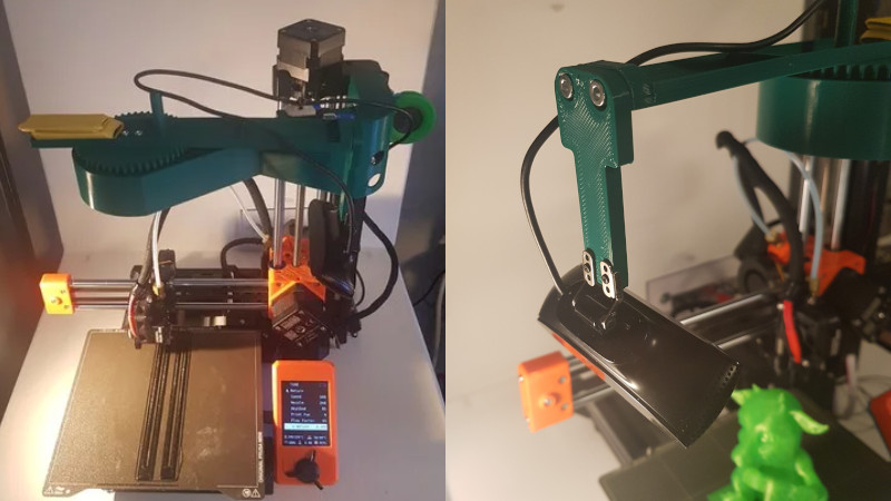
The arm relies on a 3D-printed gear train that allows a stepper motor to turn it slowly throughout the print’s duration. It’s controlled by an Arduino that receives commands via Firmata. The arm is mounted on top of the printer, holding a webcam above the build plate for a good view. It’s setup via Octolapse to take images as each layer is finished, giving that haunting look of a model materialising on the print bed throughout the duration of the timelapse.
Files are available for those wishing to build their own. The design as used is for the Prusa Mini, but it should be adaptable to other printers without too much trouble. We’ve reported on Octolapse before, with its videos proving to be the gold standard when it comes to the art of the printing time lapse.


Nice! Maybe you could add a light to the camera holder and kill the room lights so the print is only lit by the light on the arm.
I’m wondering if he would get smoother results with more gearing. The popular steppers are 200 steps per rotation. Am on a mobile phone so it’s difficult to see the gear ratio he is using. I’d be interested in the platform rotation amount in degrees vs 1 step. Then take that number and compare it to the number of layers printed.
or just use a stepper driver set to 1/8 or 1/16 step :)
Thats a general misconduction. Mechanically the cheap motors will tend to lock to the next discrete position when it come to these slow motions. It is actally visible in slow printed parts. The microstepping is for smother and more silent moves due to the incremental current changes.
I’ve got about 1000 pan steps currently, I think the gear ratio is around 15:50 or so. There’s also the gearing inside the stepper motor, which isn’t really great to be honest. I would definitly picked a better stepper motor next time.
Resembles ‘bullet time’ like in The Matrix.
Just what you need when your prints are too perfect and you need a mass on a lever to bias your extruder back and forth and left and right by swinging the load around. ;-D
But seriously, I’d think twice about doing this, ain’t printing tweaky enough without coupling extra stray motion jerks and distortions to the structure from uneven loading?
This – I’ve never understood why people are so keen to mount things on the top of the frame on printers like this – control panels, cameras, lights, even the filament spools!
The lighting sucks. The idea is cool. Also, don’t mount it to the printer and get in a bit closer so you can see it better.
I can get in a bit closer, but not much without having the camera bump the print head or losing the sides of the print unfortunately. The lightning indeed needs some improvements. The one IKEA light that is there definitly doesn’t cover everything. I’m gonna try to figure something out for that soon.
Search the usual Chinese import sites for “vlog lights” “vlogger”, “vlogging”, something like that. You should be able to find LED panel-type lights for about USD $10 on up, and you can print your own little tripods to hold them. If your camera mounting arm can manage the extra weight, a ring light gives good, consistent lighting without distracting shadows. You could even trim up a handful of cheap LED light strips and fasten them along the bottom of your pivot arm.
The more steady lumens you can provide, the more it helps hide weird transient lighting artifacts (such as if you open a door to enter the room while it’s filming, or the sun goes behind a cloud.)
@targetdrone: Thank you for the advice, the light is working great. A different camera arm made the time lapses a whole lot more stable: https://www.youtube.com/watch?v=fQDmzdyj3jE
Minimize the mass – everywhere! The same people with ringing issues that they try to solve in software or who complain about speed have printheads with high mass and heavy setups around it. I tend to think the Reddit crowd hype is holding back a lot of consumer printing improvements. No industry calibration std. – Use a Benchy? Huh? Too much focus on the software side and not enough on basic mechanics and inertia. Example. Jerk is not defined by the proper physics in Marlin. It does meet the definition of jerk which is the first derivative of acceleration. So why call it jerk and mislead? Too many hacks and not enough physical understanding. It’s like the cosplay group is driving the train.
I’d suggest you don’t want to reduce the mass of most components on the 3d printer.. Just the head/moving bed/gantry type parts. You want the frame in general to be nice and massive, which on its own reduces the magnitude of any ringing, and if its going to be massive, it might as well be made of stiffer structural material (heavier is not always stiffer, but as most printers are 2020 extrusion type frames it usually applies well here) or thicker beams of the same material, further reducing the fast head moves impact on the frame..
Also as it is easier to control the accelerations than create super lightweight extruders that work well at all temperatures, with all filaments, and you still need the head that extruder is mounted on to be stiff enough as well… Mass in the working end isn’t your friend, but it still can be better to deal with having it than compromise everything else..
Can’t say I see the point of this camera rig, but it shouldn’t matter to print quality as the whole point is the camera moves slowly and smoothly – which will make very little if any difference to the frame at all – It really shouldn’t make any as if a slow, low mass object being orbited does noticeably flex the frame isn’t fit to handle the faster higher mass print-head anyway. Though it doesn’t look to really move as smoothly as it should (a belt drive would likely be better, failing that involute tooth forms on the gear would help (if its got ’em I didn’t notice)).
A good point on the industry standard calibrations – though I’d say the print in place test mechanisms with various tolerances are a good standard.. Think MakersMuse created the best test version I’ve seen, simple concept though.
I’d also say I agree with you to some extent on where the focus lies, but part of that is because a focus on software makes cheap printers which can’t be stiff, solid printers much better. And still improves for a better quality machine.
Given that I’ve just entered into the wonderful world of 3d printing, and got my Ender 3 pro, to stop coughing up plastic hairballs; 😸 i can understand the concerns of jerky, lopsided printing. If this is such a concern, why not just counterbalance it, with a couple of neodymium magnets on the opposite side? Not big ones mind you, because of the magnetic force will want it, to attach to the frame, but just small enough to balance the whole assembly again. ( comparable to the gyroscopi. Balancing of steadi-cam’s). 😉
Totally agree. You already have a printer that is not very rigid. Don’t add more mass up high.
I tried my best to keep it as light as possible and balanced, but you are right. Especially with the mini’s one arm setup it can impact the print quality. Although, I haven’t noticed it yet, but that might be because I generally print more structural parts. And I can easily disable the arm when I don’t need it or want to print accurately :-).