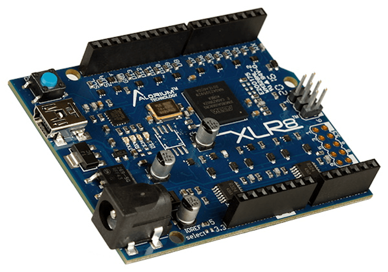
FPGA guru [Max Maxfield] recently took a look at the XLR8 (pronounced accelerate) board from a company called Alorium. On the surface, it looks like another Arduino UNO clone. But instead of a CPU, it contains an Intel MAX10 FPGA that runs a softcore AVR processor. Of course, that’s only part of the story. If the board was just a mock Arduino using an FPGA, that’s not very interesting for practical purposes. However, by incorporating accelerator blocks or XBs, you can add FPGA modules to the soft CPU. [Max] shows an example that you can see in the video below where an FPGA block controls servos more easily than a standard Arduino. There’s also a version that looks like an Arduino Nano, but can clock much faster as well as use the XBs.
In addition to prebuilt XBs, there is a workflow to build your own if you are familiar with working with FPGAs. The products aren’t exactly new, but we enjoyed [Max’s] take on the product. We also appreciated the simple code examples showing exactly how you would convert a program to use the accelerated functions.
The idea isn’t new or original, of course. You might argue that Arduino’s official FPGA support should have worked like this. The comments on the post also talk about several similar boards from earlier that never gained much traction, including ZPUino.
We talked about the nano-like board a few years ago. We’ve seen projects with the ZPUino before, too.


Cool, so you can do with it everything that you could do with a Propeller chip in 2008, except that it costs… slightly more?
i think an fpga gives you significantly more functionality than a propeller.
Absolutely but we are waiting for:
“””
In the near future, we plan to provide access to enough source code and documenta3on to make it possible for someone proficient with Verilog or VHDL and Altera’s Quartus Prime soSware to create their own XBs. The sky’s the limit on what can be done, and the XBs created this way can be shared with the rest of the XLR8 community
“”” https://www.mouser.co.uk/datasheet/2/778/aloriumtechnology_XLR8%20Product%20Brief-1217811.pdf
I’m still waiting on the “near future” Gameboy Workboy…
Heck, I’m still waiting on the Arduino Due to get proper USB host support.
Hate much? Can we all agree that a significant amount of work went into this and that in and of itself it’s a cool exercise?
i mean, they’re both approaches to high-performance and configurable peripherals. if you look at pi pico, that’s another approach to the same problem. but they’re very different approaches.
and of course the other big difference is that this is some sort of arduino…i hate arduino, but a lot of people love it. being positioned in the tool ecosystem that way definitely has an effect, it’s not nothing. it certainly makes it way different from propeller, which was awesome but stood alone. fwiw, i never got to use propeller on a project.
personally, PICs tend to have just the set of peripherals i need, or i need something much bigger like a pi with its integrated HDMI out.
Nothing “slightly” about it. They’re $75 each.
i kind of like it, but sticking with the arduino clone layout (which ive always considered horrendous) is kind of a mistake. seems like the fpga would have more i/o than that. i guess they wanted shield compatibility. but i find it a little limiting myself.
I never considered Arduino, or any of the ‘board’ platforms, as anything more the development tools. You play around with your project idea, until you a reasonably happy. Using these development boards, as the final project, is only slightly better, than leaving a project on a breadboard. Functional, but not exactly a finished project. I do have several of those breadboard projects sitting around. None were really going to be more than one off, or used much. Not really worth the extra work to produce a board. Could see scrapping them, if I need some of the parts, or the breadboard.
Unless you’re making enough to bother with professional assembly, using dev boards is the easiest way to get high reliability, unless you’re really good with an iron.
totally agree there. i find myself preferring cheaper dev boards when i intend to ‘leave it in’ the project as a permanent fixture. this makes pricy dev boards like this one a hard sell as a module. as a development tool however its fine. in either case i still prefer the gumstick form factor because you can plug it directly into a bread board or solder it protoboard, or socket it into a custom pcb with headers. the arduino form factor usually just dangles off the project by jumper wires and is very messy to work with.
of course for most of my projects, the chase is better than the catch. so i build something, it kinda works, and then it gets chucked into a box of finished projects and probably salvaged (or disposed of when i feel like i have too much stuff).
I think the “Arduino Uno” form factor was a mistake.
The original “Arduino form factor” was defined at a time when an Arduino had a DE-9 RS232 connector and entirely through-hole components with no SMD in sight. It’s old and obsolete. Not to mention that stupid pin spacing.
Today, a standard rectangular DIL form factor on a narrow board is the winning option. Think Adafruit Feather boards, the newer official Arduino hardware, or the Raspberry Pi Pico. This is what they should have chosen.
And why do we need yet another FPGA development board, anyway?
And XLR8 depends on proprietary Quartus tools that are only officially supported on Windows, and untested but supposedly working on Linux. MacOS is unusable.
Something like a Lattice iCE40HX1K iCEStick costs $50 and can quickly and easily get you up and running with a free, open source toolchain writing and synthesising Verilog onto the FPGA, on MacOS or Linux or Windows. It has plenty of I/Os and blocks for a beginner FPGA user, it’s unlikely the user will need heaps and heaps of gates in this context.
I agree with you that it would be better if they had used one of the parts for which there is a full open source flow, but I think that they would need a chip with more LUTs than the 1k device. While the user may not require all that many LUTs for their peripheral controllers/accelerators, they would need a good number to implement the soft core AVR. But there are plenty of other chips in the ICE line which would probably work, or you could even use an ECP 5 or a Xilinx series 7 part for which there are also open source Verilog to bitstream projects.
For Xilinx 7 – is the Symbiflow support chart severely outdated, or is it still only “partial” BRAM support with the definition of “partial” not provided anywhere?
Too bad Xilinx 7 is also missing DSP support in Symbiflow still. Also, Project X-Ray states “Current the focus has been on the Artix-7 50T part.” but the majority of Symbiflow’s “recommended” boards are Zynq-based? (Actually, it looks like they did update THAT, removing all but one “supported” Zynq board, and only listing one of the TinyFPGA variants, one of which has gone into solid vaporware stage at this point with no news whatsoever since March 17, 2019 – https://www.crowdsupply.com/tinyfpga/tinyfpga-ex )
Why even bother with the soft core atmega328?
Just put a real atmega328 onboard for the Arduino fans and wrap a smaller FPGA or CPLD around the atmega328 between the IO pins / serial / ADC / level translators and the actual atmega328.
This way you have a wide choice of what smaller FPGA/CPLD to use and can make it at a much lower cost. The overall development process would be so much simpler.
I write HDL and I use Arduino’s from time to time. As this board is now, there is absolutely nothing about it that in any way appeals to me, especially the price.
Speed. You can clock avr core in FPGA much faster. Also – you are not limited to amega328 – you can put bigger avr core there without any changes.
Interesting idea, but they’ve shot themselves in the foot with the price. At $75 you can get an Arduino Vidor 4000 (a SAM21D microcontroller plus an FPGA on a single board) for less money. Even Intel make a cheaper Arduino compatible board based on the MAX10 for about 2/3rds of the price.
Whatever the pricing is, they product is perfectly adapted for all those who claim “can be done with an Arduino”.
Well, I prefer waiting for the softcore massively parallel 555 to purchase some of those boards.
challenge accepted, but is HaD coverage guaranteed….?
Make an arduino shield for a Gowin? Those FPGA boards sell for 5EUR.
With arduino boards increasingly using FPGAs and MCUs supporting LUTs it’s getting pretty dumb that we can’t all program them as transparently as we can CPUs.
This protectionism has to stop. I could understand it in the earliest days when IP really mattered, but today the basics are well understood and what we really need is open source tools that can do end to end synthesis, because relying on pre-built logic blocks is unacceptable: it just cripples the tech out of the box.
but there are opensource tools that do end to end synthesis…
> but there are opensource tools that do end to end synthesis…
For the Altera MAX10?
For synthesis, yes ? http://www.clifford.at/yosys/cmd_synth_intel.html
But to write the generated bitstream you will need to use Intel’s tools.
That’s only synthesis, there is no place and route (and therefore no bitstream generated, so definitely not end-to-end). There is open source PNR for some small Lattice chips, some work in progress for cheap-ass Gowin, and some support for Xilinx series 7 – but that’s all.
@tilk
For now, YES. You can only synthesis/convert from a high level hardware language into gates and the last two steps converting from gates into a bitstream and writing that bitstream to the chips currently require proprietary tools.
But Intel is a member of CHIPS Alliance (Common Hardware for Interfaces, Processors and Systems) just like QuickLogic. And quicklogic has fully embraced open source, so much so that DARPA has embraced them and added them to their Toolbox Initiative (As well as restricted sale of some of their devices worldwide). So it may only be a matter of time before Intel does something Intelligent.
ref: https://symbiflow.github.io/
ref: https://ir.quicklogic.com/press-releases/detail/573/quicklogic-joins-darpa-toolbox-initiative-to-provide
P.S. Instead of “write the generated” I meant to put “write and generate the”, I’m blaming it not enough coffee, or not enough sleep.
The main problem is that the Arduino libraries are trying to be “helpful” and enable all sorts of interrupts by default, and this clashes with the servo library timing. The delay functions for example, which shouldn’t be used with timing critical applications because they secretly interrupt the code to increment a counter. Another is the serial port library, which keeps a 128 byte FIFO using an ISR whether you need it or not.
These “features” are poorly documented, tedious to bypass, and most users are left guessing what the problem is when things glitch out. This is why, when you want an Arduino to do something useful, you either use a separate shield with a driver chip for the thing you want, one for each thing and pay more money for the pleasure, or you ditch the Arduino core and just do it yourself.
Using an FPGA on the side falls in the first category. The AVR is perfectly capable of doing the job, but the Arduino ecosystem treats it less like an MCU and more like a poor man’s PLC.
I have a set of Arduino library replacements that might interest you, most are highly configurable.
For example, the serial module has a configurable FIFO and doesn’t have to be loaded if not needed. The Servo module is configurable for up to 4 servos.
All configuration is by #define manifests, so is very efficient. They are bare metal functions, so there’s that…
https://hackaday.io/project/177652-arduino-libraries-and-test-programs
Thanks, but…
“For example, the stepper interface can be configured to use any three GPIO pins (step, dir, enb).”
My latest project uses cheap off-the-shelf transistor buffers with four pins for drivers, and I’m doing a simple half-step pattern with it.
I find that using someone else’s libraries, they either don’t do exactly what I’m doing, or they go behind my back to do extra stuff that I don’t want, and I end up chasing someone else’s bugs and poor documentation. The more cases and functions you try to capture with your library, the more difficult it becomes for someone else to disentangle and find out what it actually does by reading the source.
I’d rather have a library of code examples that each do something directly, and modify from the examples, because then I can know what I’m doing and what’s happening.
Now we just need an FPGA development environment that’s as simple to use as Arduino for microcontrollers.
you don’t need FPGA to do servo control, a 328P does it fine! I’ve never seen that type of jitter, I suspect the software library he is using has some issues, or something silly is going on (like writing to the serial bus while he is doing it).
and of course I meant stepper!
The Arduino millis() function uses a timer interrupt to count how many milliseconds has passed since the system was reset (not really, the frequency is a bit off). It also interferes with your interrupts, screwing up any precision timing.
You have to disable it by clearing the TIMSK0 register first, and then not use the servo library because it’s silly and there are far better ones.
What if you want/need to write to the serial bus while doing servo commands?
Any microcontroller can do jitter-less servo control if that’s the only thing it’s doing, but that’s not exactly helpful. In the real world we might need to scan for user inputs, read other comms based sensors and write to LCD / OLED screens.
Often the jitter doesn’t matter, but when it does it would be nice if it didn’t take a week to customise all of the libraries to play nicer with each other. I have seen (and heard) the servo jitter myself and it’s good to see solutions to this.
There are plenty of FPGA boards with Arduino headers (eg. Digilent ARTY series). If you want to shorten the list, the first thing to look for is: 5V tolerance.
There are plenty of Arduino shields that use 5V logic, along with the 5V pin on the header. If your FPGA board doesn’t have level translation, you can kill it without even a puff of magic smoke.
Since this product is driving servo boards, it’s probably capable of handling 5V logic. That, in itself, is more important than anything else mentioned in the article/
Why?
Who could this possibly appeal to?
Even a board with this footprint and a real atmega328 AND a small FPGA or CPLD would be better.
If you want to learn a HDL and integrate some Arduino code then this board is definitely NOT for you. You would be trapped into wading through someone else’s complex HDL and trying understand it well enough to seamlessly integrate your own HDL. The existing HDL may not even be your chosen HDL.
Then when things don’t work quite right … Is it in the Arduino code or your HDL or even perhaps you screwed up some of the original HDL while editing it. Good luck debuging that.
If you have a more complex project that needs a bit of parallel signal processing in hardware and greater throughput then you wouldn’t even consider an 8-bitter for the task, nor would you be looking at anything Arduino based.
With a typical analog servo, you only need to generate a 1.5-2.5 ms pulse every 20 milliseconds and the rest of the time you can do anything you like. To signal your servos, you set the Timer1 to count at a microsecond resolution and make it fire off two interrupts: one for pin up, the other for pin down. The pin-up routine fires every 20 ms and resets the counter to zero, so the pin-down can fire at the right moment for the correct pulse width. If you want two servos, fire it off every 10 ms and keep alternating the pin you’re toggling. Three, four, up to eight servos is easy this way and the exact repeat frequency isn’t crucial, so you can squeeze in one more, or update slightly faster to make the servos more snappy.
The problem is that the Arduino fires an ISR every millisecond to service the internal time counters and this keeps blocking your interrupts, which generates the jitter. If you’re receiving something through the UART, this also keeps blocking your interrupts because the Arduino insists on catching the data available interrupt and putting it in a buffer.
Now, you can deal with the first problem by disabling the interrupt, but you can’t do anything to the other problem without completely gutting the serial library. What you want to do is to poll the 2 byte HW serial buffer every 1-2 ms to keep up with 9600 baud, and you need to do it in the dead time of your interrupts, which would be easy if you had control over all the timers and interrupts, which are taken up by the Arduino core libraries. One hacky way to deal with it is to use the hardware flow control bits (are they supported? How?) to block the PC from sending anything while you’re expecting your interrupts to happen.
In other words, by trying to do too much to help its users, the Arduino ecosystem ends up doing less for them, and making it more difficult to access the basic functions of the hardware.