We wonder if [Carl Bugeja] was looking at a 3D printer’s heated bed when he got the idea to create a PCB reflow heater using a PCB. He tried a quick test to heat up a standard PCB and made it self-reflow. That worked, though it obviously wouldn’t be practical for all boards. But it proved he could make it work.
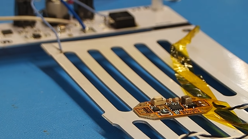
To improve the heating performance, he laid out a metal core PCB, along with some custom control electronics. The board’s resistance didn’t quite perform to calculations, but luckily, it was too high so a shunt wire was able to reduce the overall resistance. One important thing to consider is that the heater board needs to use higher temperature solder so it doesn’t desolder its own components
We were glad to see [Carl] use a metal core board as standard PCB material can get cranky at high temperatures over 130C. Even so, it would be good to check the boards you plan to use this way to make sure they are rated for the kind of temperatures required.
We’ve seen lots of reflow heat sources. Halogen lights come to mind. Or, raid the toy closet and find an Easy Bake oven.


I wonder why the hotplate method of reflowing (like this basically is) isn’t used more often. For me it has been much easier to get good results with it than using a DIY reflow oven, and a hotplate takes up much less space also.
The biggest downside seems to be that big PCBs are often a bit curved, leading to poor thermal contact.
Isn’t that what hot sand baths are used for then?
Because it can be considered very harsh conditions. I tried it once because of the lack of other possibilities to solder a BGA. The PCB warped a few mm after placing on the plate while heating up. I consider this only in an emergency.
Didn’t happen to me… Were those really big PCBs or maybe not the best quality substrate?
about 10*12cm. The hot plate was in reality an upside down mounted clothes iron set to max. temp. Just sufficient to melt SnPb solder.
Did you set the PCB on the cold plate and heat it up (longer heat influence time) or (like we did) put it on the already hot plate (stronger thermal shock but shorter hot time). That will of course make a difference.
I use an 5mm thick straight cold rolled steel plate on my ceramic glass cooktop. I put the PCB on quite a bit before the plate reaches the solder melting point. Don’t know exactly but it around 30-45s before the soldering process starts. I have a cold plate of same thickness next to it, so I can slide it on there without any dangerous handling…
I put PCB on cold plate. I’ve selected the heating setting to result in about 3 minutes from cold to solder melting, which is similar to recommended reflow profiles (though not as precisely controlled).
Yo, dawg! I hear you like PCBs…
Seeing those slots milled into the metal core PCB makes me wonder if anyone has used it as a front panel. I’ve seen it done with FR4, but having an aluminium plate would take it up a notch.
To answer my own question, yes!
https://www.youtube.com/watch?v=gSio28SH38E
…luckily the resistance was too high so he used a shunt wire…
WTF? That doesn’t work. “resistance too low” I can see, but voltage across any resistor in any set of shunt (parallel) resistors will be the same.
Truthfully I can’t be bothered to watch the video to find out what reality is… to me it’s yet ANOTHER article with a link to a video that the ‘journalist’ may (or may not) have watched.
That’s so funny. He has the “winding trace” resistor pattern so if you short out some of the “coils” (yes, they aren’t really coils) then you have less copper in the path and thus less resistance. I’m not sure how a shunt wire ever fixed too low resistance in this configuration.
Ahh yes… meaning if the resistance was too low a *series* resistor could be inserted. I didn’t want to fill my response with detail that just makes me seem like I’m carrying on un-necessarily.
I stumbled on this by accident once upon a time. We had some assembled boards with what appeared to be internal power plane shorts and no amount of inspection could reveal where (I’ve since used x-ray to drill them out but this was a while ago). I could blow them out with a car battery but the patient did not survive the operation. I pressed a 50A adjustable power supply into service and slowly ramped up the voltage. At some point – a few volts? – the entire board suddenly reflowed. It was fun to see all the parts (which had been hand-soldered) suddenly line up. I was not able to find the short though. In retrospect I should have used a TIG welder as the supply, could have pulsed it on at higher power with the pedal and maybe found a ‘just right’ setting.
sounds like you just invented a new reflow soldering technique. Just put some winding traces in a spare layer and away you go!
Nah… I just include heating tracks in all my PCBs. So every PCB can reflow itself by connecting it to lab PSU. Just need to set PSU to some reasonable wattage per PCB area.
That’s honestly what I thought he was going to be doing when I read the title.
I’ve made PCBs that desolder themselves if that counts…