Interruptions aren’t just a staple of our daily lives. They’re also crucial for making computer systems work as well as they do, as they allow for a system to immediately respond to an event. While on desktop computers these interrupts are less prominent than back when we still had to manually set the IRQ for a new piece of hardware using toggle switches on an ISA card, IRQs along with DMA (direct memory access) transfers are still what makes a system appear zippy to a user if used properly.
On microcontroller systems like the STM32, interrupts are even more important, as this is what allows an MCU to respond in hard real-time to an (external) event. Especially in something like an industrial process or in a modern car, there are many events that simply cannot be processed whenever the processor gets around to polling a register. Beyond this, interrupts along with interrupt handlers provide for a convenient way to respond to both external and internal events.
In this article we will take a look at what it takes to set up interrupt handlers on GPIO inputs, using a practical example involving a rotary incremental encoder.
Some Assembly Required
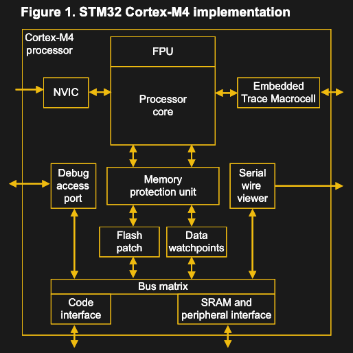
Interrupts on STM32 MCUs come in two flavors: internal and external. Both types of interrupts use the same core peripheral in the Cortex-M core: the Nested Vectored Interrupt Controller, or NVIC. Depending on the exact Cortex-M core, this peripheral can support hundreds of interrupts, with multiple priority levels.
These interrupts are not all freely assignable, however. If we look at the reference manual for the STM32F4xx MCUs (specifically RM0090, section 12), we can see that for the NVIC interrupt lines, we get whittled down to 82 to 91 maskable interrupt channels from the up to 250 total for the NVIC core peripheral in the Cortex-M4.
These interrupt channels all have a specific purpose, as defined in the vector table (e.g. RM0090, Table 62), which has over 90 entries. Some of these interrupts are reserved for processor, memory or data bus events (e.g. faults), while the ones which are usually most interesting to a developer are those related to non-core peripherals. Just about any peripheral — whether it’s a timer, USART, DMA channel, SPI, or I2C bus — has at least one interrupt related to them.
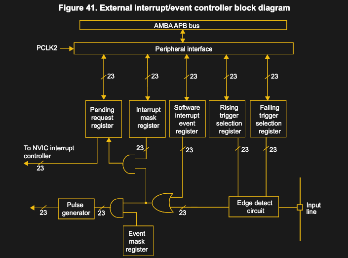
The same is true for the EXTI (EXTernal Interrupt/event controller) peripheral. On the STM32F1, F4, and F7 STM32 families, the EXTI peripheral has 7 interrupts associated with it, and 3 on the F0 (STM32F04x and others). For the first group, these are described as:
- EXTI line 0
- EXTI line 1
- EXTI line 2
- EXTI line 3
- EXTI line 4
- EXTI line 5 through 9
- EXTI line 10 through 15
As one can see, we get 16 lines on the EXTI peripheral which can be used with GPIO pins, but some of those lines are grouped together, requiring a bit more work in the interrupt handler to determine which line got triggered if desirable. The lines themselves are connected using muxes to GPIO pins as in the following diagram:
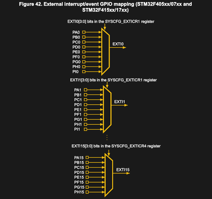
What this means is that on the F1 through F7 families, GPIO pins 0 through 4 get a dedicated interrupt which they share with other GPIO peripherals. The remaining 11 pins on each GPIO peripheral get grouped into the remaining two interrupts. On the STMF0xx family, lines 0 & 1, as well as 2 & 3 and 4 through 15 are grouped into a total of three interrupts.
The remaining EXTI lines are connected to peripherals like RTC, Ethernet, and USB for features like Wakeup and Alarm events.
Demo Time: Incremental Encoders and Interrupts
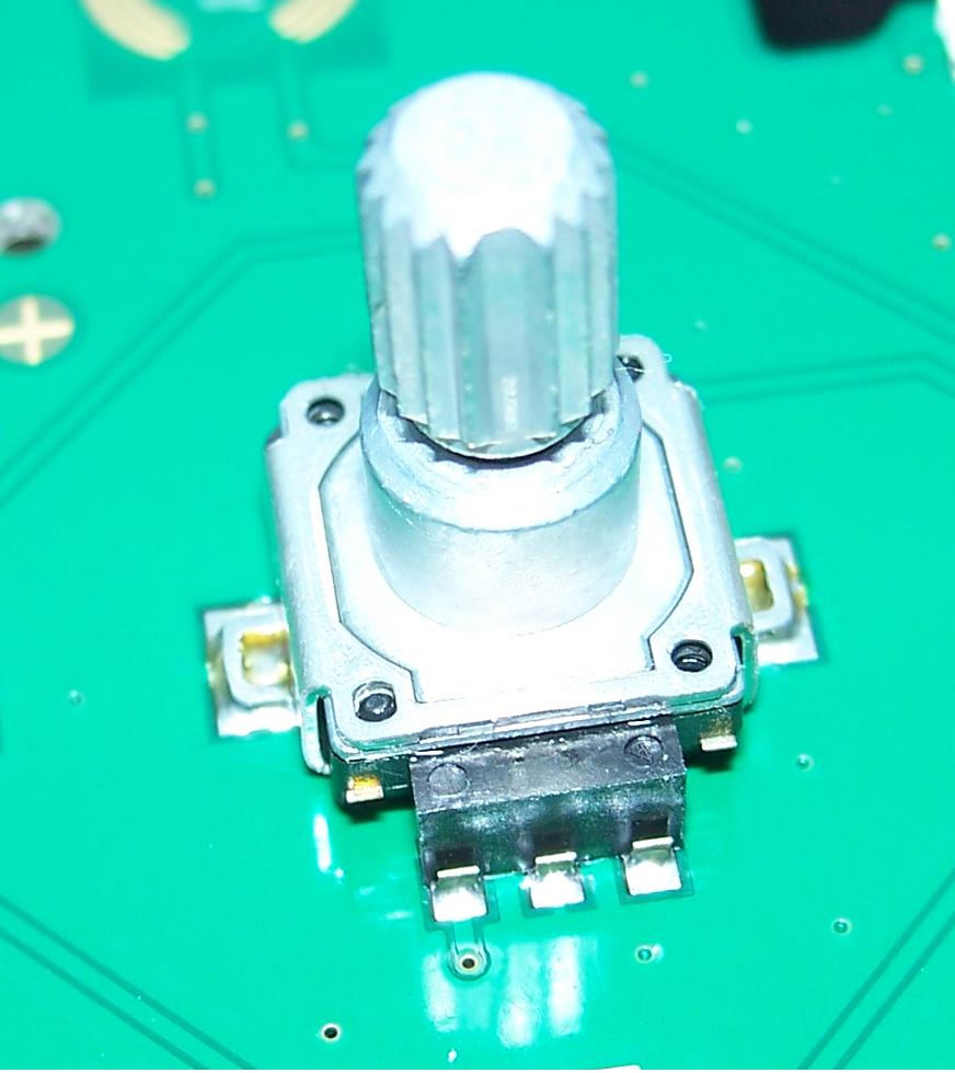
The way that mechanical rotary incremental encoders work is that they alternately create a contact between the single input pin and the A & B output pins. The result is a pulsing output from which one can deduce the rotation direction and speed. They are commonly used in control panels, where an additional two pins provide a push button functionality.
In order to properly sense these pulses, however, our code that runs in the MCU has to be aware of every pulse. Missed pulses will result in visible effects to the user such as a sluggish response in the system, or even a direction change that doesn’t get picked up immediately.
For this example, we’ll use a standard rotary encoder, connecting its input pin to ground, and connecting the A & B pins to GPIO inputs. This can be any combination of GPIO pins on any port, as long as we keep in mind that we do not overlap with pin numbers: if we use, say, PB0 for signal A, we can not use PA0 or PC0 for signal B. We can however use PB1, PB2, etc.
Setting Up External Interrupts
The steps involved in setting up an external interrupt on a GPIO pin can be summarized as follows:
- Enable
SYSCFG(except on F1). - Enable
EXTIinRCC(except on F1). - Set
EXTI_IMRregister for the pin to enable the line as an interrupt. - Set
EXTI_FTSR&EXTI_RTSRregisters for the pin for trigger on falling and/or rising edge. - Set
NVICpriority on interrupt. - Enable interrupt in the
NVICregister.
For example an STM32F4 family MCU, we would enable the SYSCFG (System Configuration controller) peripheral first.
RCC->APB2ENR |= (1 << RCC_APB2ENR_SYSCFGCOMPEN_Pos);
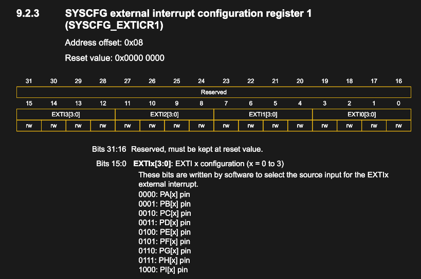
The SYSCFG peripheral manages the external interrupt lines to the GPIO peripherals, i.e. the mapping between a GPIO peripheral and the EXTI line. Say if we want to use PB0 and PB4 as the input pins for our encoder’s A & B signals, we would have to set the lines in question to the appropriate GPIO peripheral. For port B, this would be done in SYSCFG_EXTICR1 and SYSCFG_EXTICR2, as each 32-bit register covers a total of four EXTI lines:
While somewhat confusing at first glance, setting these registers is relatively straightforward. E.g. for PB0:
SYSCFG->EXTICR[0] |= (((uint32_t) 1) << 4);
As each line’s section in the register is four bits, we left-shift the appropriate port value to reach the required position. For PB4 we do the same thing, but in the second register, and without left shift, as that register starts with line 4.
At this point we’re almost ready to configure the EXTI & NVIC registers. First, we need to enable the GPIO peripheral we intend to use, and set the pins to input mode in pull-up configuration, as here for PB0:
RCC->AHB1ENR |= (1 << RCC_AHBENR_GPIOBEN_Pos);
GPIOB->MODER &= ~(0x3);
GPIOB->PUPDR &= ~(0x3);
GPIOB-&>PUPDR |= (0x1);
Say we want to set PB0 to trigger on a falling edge, we have to first enable Line 0, then configure the trigger registers:
pin = 0;
EXTI->IMR |= (1 << pin);
EXTI->RTSR &= ~(1 << pin);
EXTI->FTSR |= (1 << pin);
All of these registers are quite straight-forward, with each line having its own bit.
With that complete, we merely have to enable the interrupts now, and ensure our interrupt handlers are in place. First the NVIC, which is done most easily via the standard CMSIS functions, as here for PB0, with interrupt priority level 0 (the highest):
NVIC_SetPriority(EXTI0_IRQn, 0);
NVIC_EnableIRQ(EXTI0_IRQn);
The interrupt handlers (ISRs) have to match the function signature as defined in the vector table that is loaded into RAM on start-up. When using the standard ST device headers, these have the following signature:
void EXTI0_IRQHandler(void) {
// ...
}
When using C++, be advised that ISRs absolutely need to have a C-style function symbol (i.e. no name-mangling). Either wrap the entire ISR in an extern "C" {} block, or forward declarations of the ISRs to get around this.
Wrapping Up
With all of this implemented and the encoder wired up to the correct pins, we should see that the two interrupt handlers which we implemented get triggered whenever we rotate the encoder. Much of the code in this article was based on the ‘Eventful’ example from the Nodate project. That example uses the APIs implemented in the Interrupts class from that framework.
While at face-value somewhat daunting, using interrupts and even setting them up manually as described in this article should not feel too intimidating once one has a basic overview of the components, their function and what to set the individual registers to.
Using the NVIC and EXTI peripherals for detecting external inputs is of course just one example of interrupts on the STM32 platform. As alluded to earlier, they serve a myriad more purposes even outside the Cortex-M core. They can be used to wake the MCU up from a sleep condition, or to have a timer peripheral periodically trigger an interrupt so that a specific function can be performed with high determinism rather than by checking a variable in a loop or similar.
It’s my hope that this article provided an overview and solid basis for further adventures with STM32 interrupts.


Encoders are dangerous examples when it comes to external interrupts. For encoders the absence of hysteresis is a quality criterion as it allows for greater positional accuracy. This also means that tiny but high frequency mechanical vibrations can make the encoder change state rapidly. In the worst case this ends in the microcontroller getting locked down doing nothing but interrupt routines. The proper way to read an encoder is to identify the maximum speed expected and poll it in a timer interrupt fast enough to not miss steps. That said it will be fine for a low resolution encoder but I fear many apply this same principle to whatever encoders they come across and its a tough problem to debug.
Good point regarding noise but the proper way to use them would be to use the timer peripheral in encoder mode. It even has programmable filtering. No software overhead, no interrupt handlers needed.
I’ve been trying to do this with a BluePill (timer encoder mode), but it’s not triggering on all of the edges, so when the encoder “jitters”, I get the wrong count. Do you have examples proven to work on both signal edges (rise and fall of each input) for an STM32F1?
I’m successfully using a blue pill with timers in encoder mode. Took a bit of trial and error, but I think the key was setting the filter correctly. Enough filter to eliminate noise, but not so much as to miss counts at the maximum input frequency.
HardwareTimer *PitchEncTmr = new HardwareTimer(TIM1);
setTimerEncoderMode(TIM1);
void setTimerEncoderMode(TIM_TypeDef * MyTimerBase){
//Setup timer inputs 1 and 2 as encoder inputs
MyTimerBase->CR1 &= ~TIM_CR1_CEN; //Disable counter
//configure channels 1 and 2 as inputs from their respective pins
//apply the maximum filter to the inputs to filter out noise spikes from inductive EMI.
//Timer sample rate is system clock (72MHz / 32 / 8)
MyTimerBase->CCMR1 |= (TIM_CCMR1_CC1S_0 | TIM_CCMR1_IC1F_3 | TIM_CCMR1_IC1F_2 | TIM_CCMR1_IC1F_1 | TIM_CCMR1_IC1F_0);
MyTimerBase->CCMR1 |= (TIM_CCMR1_CC2S_0 | TIM_CCMR1_IC2F_3 | TIM_CCMR1_IC2F_2 | TIM_CCMR1_IC2F_1 | TIM_CCMR1_IC2F_0);//Link Inputs and apply debounce filter;
MyTimerBase->PSC = 0; //Default value.
MyTimerBase->ARR = 65535; //set the rollover value to maximum
MyTimerBase->SMCR |= TIM_SMCR_ETF_1 | TIM_SMCR_ETF_0 | TIM_SMCR_SMS_1 | TIM_SMCR_SMS_0; //SMS = 011(encoder mode); ETF = 011 (external trigger filter)
MyTimerBase->EGR |= TIM_EGR_UG;
MyTimerBase->CR1 |= TIM_CR1_CEN; //Enable counter
}
Heh yes, that’s an important gotcha.
I would however advise against using polling: spinning faster than a rather low polling rate makes the values go down again or jump around, which is rather infuriating. I had power supplies and signal generators do just that.
As a fun side note, I also used the QDEC function of Atmel SAM4N8A which is supposed to handle incremental decoding and fault detection in hardware, but it wouldn’t handle counter wrap-around and direction detection properly.
Very good observation. This is why I use small ICE40LP384 to decode high speed quadrature encoders (100KHz per channel) on the same SPI bus that allow to program it. This work very well even with a small ESP8285H16 processor. Yosys allow very easy ICE40 programming in verilog. The only problem is actually the availability of the ICE40LP384 chip in QFN32 package.
this article just reminds me how fun embedded development is. once you get the right colleciton of data sheets / user manuals (a slight challenge for the STM32 compared to PIC, but), you can really see everything. no layers. the “thread-safety” kind of questions you face when interfacing with ISRs are all very concrete, there’s no “referencing blah blah during blah results in undefined behavior.” debugging can be a huge pain in the butt but i still think it’s fun.
sad that i haven’t had a project that needed a microcontroller cross my radar in a couple years.
Have worked with 8051 controllers (hardware and software) from 1984 to 2016. Started with 8031 (Intel) *romless” with eproms then later ,1991, with 80C537 (Siemens/Lineo) Boot eprom, download Appl over the (multi master) RS485 serial line and ,2008?, uC841 (Analog Device) with flash also downloadable. Programming done in ASM, PLM and C whereby most asm ended up in .lib files. As with the arival and implentation of ethercat together with component supply problems is was going end of a era.
The multi master RS485 commumication was born out of the lack from Intel to give full details on the protocol spec (we did run out of time, afterwards we where lucky as their protocol was master-slave.
Why use interrupts to track encoder movement when the STM32 family already includes an encoder count mode on their timers?
Maybe if you run out? After all many STM32 have less than 5 timers with encoder feature. When I had 8 to read I used GPIO + DMA trick to read pin states to memory and then process them from array. This lets one have the interrupt less time-critical though it has to process more data.
“The interrupt handlers (ISRs) have to match the function signature as defined in the vector table that is loaded into RAM on start-up”
AFAIK unless remapped or in boot to memory mode the vector table is in the rom (flash).
While i appreciate keeping the example simple, two things should have been mentioned, albeit on a brief note.
Without denouncing this solution can/will lead to big problems, e.g. interrupt storms. Either denounce with filters in hardware, or disable the interrupt for a bit to let it settle (complex, a timer is easier in that case)
And maybe a wiff on what to do with the encoder interrupts. A button made have been more logical in the example. For the rotary encoder personally I like to use a lookup table to ensure only valid combinations are seen. It makes noise less of a problem too ..
The Linux kernel encoder driver from gpios for example does that too …
I’ve seen the lookup table, but I don’t see what its advantage is over a few logical ops, like so:
https://github.com/naasking/embedded/blob/master/rotary.h
I denounced the bounces but they still occured ;-)
My C is pretty rusty, could somebody please explain me those two lines from the code?
SYSCFG->EXTICR[0] |= (((uint32_t) 1) <PUPDR |= (0x1); /* what is this -&> operator doing? */
https://overiq.com/c-programming-101/pointer-to-a-structure-in-c/
Basically, if you have a structure with something in it, you can access that with
.. So likemystructure.element.But now imagine that you want to use a pointer to that structure. You could do it with straight-up pointer dereferencing,
(*mystructure_p).element. Butmystructure_p -> elementis the idiomatic way to do it. (I might have even messed up the parentheses above…I’d have to consult my C-language lawyer before I typed that into working code.)You are correct. The . operator has higher precedence than the * operator.
*mystructure_p.element should fail at compile time unless mystructure_p is a union of both a pointer to a struct which contains element and/or of a struct type which contains element.
Unions can be dangerous.
Looks like it might be a stray ampersand.
Yay mis-threading, that was a reply to the question above about the “-&>”.
IMHO, polling Is the way to go for incremental encoders which always suffer from spurious pulses. In my projects, registering 10 incremental encoder events per a second seems to be sufficient or fluid. Five to Ten times that is a low load on a CPU, I think much less load than interrupts. But importantly having precisely timed polling enables fine tuned filtering, and better reflexed response to the mechanical click.
If a wake up is required, still one signal can be used for it.
Having said all this, thanks for the post it was written very nicely!
Looks like you you are describing sampling at a constant, not polling. Polling would imply that the code is busywaiting btw the sample times.
This. As soon as I saw “Rotary encoder” I did a facepalm.
Rotary encoders should be polled at fixed time intervals, eg. 1ms. They should NOT be connected to a CPU’s interrupt pins. The same goes for any other noisy switch.
(nb. You _can_ use a timer interrupt for the polling…no problem there)
Quality article! I would like to see more of these types of articles. I was having grief getting EXTI working on my STM32 until I stumbled upon this article.
1
SYSCFG->EXTICR[0] |= (((uint32_t) 1) < I’ve probabbly missunderstood, but isn’t this for PB1?
I am writing this tutorial using stm32duino IDE. The problem is that there are functions defined with that signature already. How should I go about overwriting those?
This is a good article!
Thank you for the how-to! Wrote my program as C++ and my ISRs were not wrapped with C extern. Changed that and now timer/good interrupts are working. Thank you!