Pneumatics are a great solution for all kinds of actuators, and can even be used for logic operations if you’re so inclined. Typically, such actuators rely on nicely machined metal components with airtight rubber seals. But what if you did away with all that? [Richard Sewell] decided to investigate.
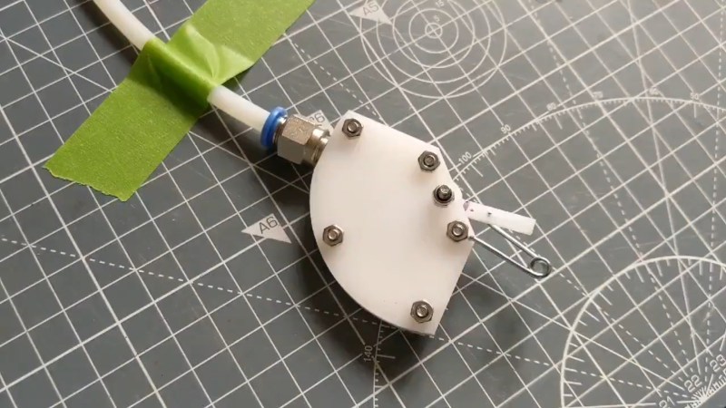
The result is a pneumatic actuator built out of lasercut acetal parts. The mechanism consists of of two outer layers of plastic acting as the enclosure, and a cut-out middle layer which creates the air chamber and houses the actuating arm itself. It’s a single-acting design, meaning the air can push the actuator one way, with a spring for return to the neutral position. The action is quite fast and snappy, too.
[Richard] aims to tweak the design further by improving the registration between the features of each layer and reduce the rubbing of the actuator’s rotor on the surrounding parts. If you’ve got the know-how, sound off in the comments. Alternatively, consider looking into soft pneumatics as well. Video after the break.
Can you make a pneumatic actuator out of lasercut acetal and hope ? And, more importantly, should you? pic.twitter.com/6ge3Ercyzi
— Richard Sewell (@jarkman) March 28, 2021
[Thanks to Robert for the tip!]


Heck, I’ll bet you can build a Roots blower using similar techniques. Adding acetal to my next McMaster order…
Yes, I’m sure you could. Might be quite leaky, and you’ll want to watch the tolerances for layer location and for the pivots, otherwise it’ll rub. Good luck!
WAIT – pneumatic logic!?!? Into the rabbit hole!
Oh, what wonders the Internet holds.
I had some air logic elements somewhere around here. I think some AND and OR gates.
Vacuum wiper motor
Wow. Blast from the past. My ’53 Jeep used a vacuum wiper motor. What a miserable pain in the butt it was. Woulda been better off using that vacuum for, oh, maybe power brakes.
When I was restoring my ’44 jeep (with the small ‘j’) one of the previous owners had fitted postwar electric wiper motors. Looking for more originality I bought a set of 1940s Trico vacuum wipers for it, as they had on jeeps during the latter stages of the war, and intended to fit.
I discussed this with one of our (very) old jeep club members who had been an army mechanic during the war (and went through the bombing of Darwin) and was surprised by his answer – “chuck ’em to the sh*thouse, stay with the electric ones!”.
Many years later, I have the vacuum ones still in their cardboard box.
I’ve got vacuum wipers on my ’64 CJ5a. They aren’t great, but it has become sort of a garage queen so it isn’t such a big deal. Interesting that they slow down under engine load though so it becomes harder to see when you go up a hill.
Theo Jansen uses some pneumatic logic in his strandbeests, even lecturing with special demo models. The NOT gates he calls “liars”.
Try copying the mechanism of a vacuum wiper motor. They automatically switch to go back and forth. IIRC some had two speed operation by having two different sized holes on the slide valve. Shouldn’t be difficult to make the thing variable speed or to construct a mechanism that moves it one way and stops then reverses when a button is pressed to switch the valve plate, which would make it move back and stop until the button is pressed.
Those vacuum motors could be quite strong with just a few PSI difference across 3 or 4 square inches of the flap.
Vacuum powered door lock actuators from 80’s Mercedes could be interesting. A rubber diaphragm separated the two sides, and a rubber bellows like boot sealed the output shaft. Not snappy though.
To properly stack the layers locating pins could be used. You can get properly precision ground pins but may be just press fitting some nails may do the job. Using something that does not have a thread as axle should also help.
In general screws can (should) not be uses as location devices. They are for providing clamping force only.
To improve sealing at the bottom the actuator arm could be bend to become springy in this direction. Then it would rub against the bottom and seal tight even if the tolerances are not that great. Getting the stiffness right without weakening the actuator too much will require a bit of try and error. It will also require more space in the chamber but that should not be a huge issue.
Yes, I think the easiest solution for location and clamping is probably bolts inside little bits of brass tube. Easy to make, and works for both attaching the layers and the pivot.
The spring end solves the actuator end, but I suspect the sides are more of a problem. It may be that adjusting the thickness of the clearance-providing tape would help with that.
I wonder if the hinge could be replaced by a flexure. This would make the actuator even easier to assemble and would get rid of one of the big leaking points. It took me a while to realize that it is fine if the “hinge” is only attached on one side as the second chamber is not pressurized and doesn’t need sealing.
One could glue or screw a stripe of stiff plastic foil to the arm to seal the gaps to the top and bottom layer. No idea how long such a thing would last, though. The question is how much effort is worth putting into adding seals. At some point it is probably easier to just use a syringe or a tube with plunger and an O-ring.
Moving the end stop to the bottom of the arm would seal this end when the actuator is moved at the end position. The outlet “valve” can easily be moved where the end stop is now.
Yes, the second chamber needs a big vent for the thing to work at all.
A flexure would be good for sealing, but it’s hard to get a large angle from a flexure, and it’s hard to get a solid pivot location. Might be feasible for a small-angle actuator, though.
Won’t solve your problems, but on flexures, I was always fascinated by flex pivots: https://flexpivots.com/riverhawk-companys-flexural-pivot-product-line/
A frictionless bearing flexures pivot.
For alignment, building the flexing into a laser leaf spring that pushes a locating pin against a fixed face takes out the diametral tolerances. I’ve seen these in laser cut clock kits my kids got for gifts one year.
I like bellows over sliding seals since they don’t need precision smooth or lubricated surfaces like sliding seals.
Yes, those are lovely. And in a 3-layer lasercut stack there might actually be enough parts to make that structure of flexure. Acetal isn’t too bad for flexures (eg, https://photos.app.goo.gl/U2HuQfkNfwAzezzp7). Think you’d be restricted to quite small angles, though.