If you really think hard about it, a CPU is just a very general-purpose state machine. Well, most CPUs are, anyway. The MC14500 is a one-bit computer that has only 16 instructions and was meant to serve in simple tasks where a big CPU wouldn’t work for space, power, or budget reasons. However, [Laughton] took the idea one step further and created a single-bit computer with no real instructions to control a printing press. The finished machine uses a clever format in an EEPROM to drive an endless program.
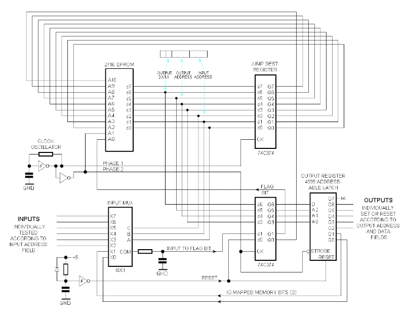
Honestly, we’d say this is more of a state machine, but we like the idea of it being a minimal CPU which is also true. The design uses the EEPROM in an odd way. Each CPU address really addresses a block of four bytes. The byte that gets processed depends on the current phase and the status of the one-bit flag register.
Each four-byte block has two sections. There are two instructions that read inputs and sets outputs. The first instruction executes if the flag register is false and the second executes if the flag register is true. All of the inputs and outputs are, of course, single bits. The second pair of bytes are two addresses for the next instruction. Again, the first instruction is for a false flag register and the second is for a true flag register.
The I/O is a bit peculiar. Each phase 1 instruction selects an input to store in the flag register and can set or clear one of 7 output bits. Of course, you might not want to write an output on each instruction, so there is an eighth bit that isn’t connected. Writing to it has no effect.
There’s no actual RAM memory, but the design loops back two output bits to the input bits so that you can store two bits and read them back later. Really, sort of an EEPROM-based state machine but still a fun idea. We’ve seen a few MC14500 builds, too, if you want to find out more about what inspired this machine.


Old 2716 trick used to be driving 7-segment displays by putting in the segment combinations at each address point and multiplexing the output. That of course was when they were plentiful. I still have about 25 of them in my chip tray – don’t know why. Seems a shame to get rid of a device that’s so easy to use. But you could program for things like hex output, so that was cool.
Yup, using parallel I/O (E)(P)ROMs as a look-up table (LUT) is a time-honored way to implement any combinatorial logic you want as long the # of inputs is <= # of address bits and the # of outputs is <= # of data bits. Hold onto the 2716's, I say.
I had an old TV tuner that use analog voltage with a bank of pots to set channels.
I built an “Digital” version using a 2716 + 8-bit DAC + counters that display channel on a 2 digit 7 segment display, output the corresponding values to the DAC and change (off the air) channels from a push button.
A previous reference: https://hackaday.com/2014/04/20/the-computer-without-a-cpu/
(that one lacks the “MC14500” tag)
Thanks for a great site and the very interesting articles
Best regards,
A/P Daniel F. Larrosa
Montevideo – Uruguay
>that one lacks the “MC14500” tag
Creator here. Too bad *this* reference is tagged with MC14500! Al Williams, any chance you can remove that tag (or clarify your text)?
I kinda regret ever mentioning the 14500 in the original description on my web page. My little contraption has received a lot of attention online, and I’m grateful for that, but it’s amazing how many folks (including a few in this thread) fail to notice that my device does *NOT* use a ‘4500. 8-0
Wow, that’s a blast from the past, We used one in the electronics option of my physics degree.
I have lots of 1 bit CPUs around the house. Their called light switches.
a one bit cpu is about the simplest possible computational circuit, though it doesn’t look that way with all the parallel eeprom address lines. I guess if you wanted to simplify it farther and dispense with those you would need to use a mercury delay line.
I just wonder if somebody took the time to convert this into VHDL – and suddenly you are about more than a million times faster …
Creator here. A buddy of mine who was bored one day *did* convert this into VHDL (or was it Verilog?). But IMO that loses some of the charm, which has to do with how a 32-bit instruction unit gets accessed despite the physical reality of an 8-bit wide EPROM. On FPGA, all 32 bits are simultaneously accessible, which to me seems too easy! ;o)
BTW, the super low clock speed was chosen because I used a NOP sequence for a time delay. I’m sure the machine could run a LOT faster than 60 Hz. But then the NOP sequence would’ve been too large to fit in memory!
back in the day, we called this sort of thing microprogramming and the stuff in the eprom was called microcode.
Something that works the same way (and is more common to some of us) is the Apple Disk ][ Controller from the original Apple II.
It abused an 6309 PROM (P6), a ‘323 parallel input shift register and a `174 flip-flop to build a 4-step-state-machine to read the disk flux faster than the 0.6-1.0mHz CPU possibly could.
More info here (9th paragraph down): https://paleotronic.com/2018/05/19/steve-wozniak-talks-disk/
Very nice. This is the comment I was looking for. I distinctly remember the moment I figured out how the Disk ][ controller worked and it was magical.
you have to take a look at https://github.com/olofk/serv
its a bitserial Risc V core ^_^
I once built a lift controller using this chip. The controller used contacts wired in parallel on each floor to indicate when a new floor was reached and two extra contacts, one at the bottom to calibrate the floor counter and one at the top to prevent the lift trying to break through the roof.
When turned on, the controller would recalibrate by sending the lift downwards until the bottom contact was closed, which would also reset the floor counter. Going up, each closure of a floor contact would increase the counter and going down each floor contact would decrease it. There were also contacts to check that the doors were fully closed.
The whole setup worked flawlessly, it seemed, until I realised it had a minor problem: When turned on it would recalibrate (yes, I know I said it before) but — and what a BUT it is — it would not check that the door were closed and not issue the command to close before it set off downwards.
Oops!
Luckily, I found this fault during testing and no elderly ladies were harmed in the process.
I used a MC14500 back in 1979 to control a peltier device. It does run at 1MHz if you need a faster clock.
Just a reminder for those of you who haven’t noticed — the One Bit CPU I created does NOT use an MC14500!
Indeed. I read your article. Some genius work there. Have you done any interviews about your career? I’d love to listen or read more.
Glad you’re enjoying the work — I too had some fun with it! There’s some other interesting (to me) stuff on my web site, of course. And if you feel like digging a little deeper have a look at the previous version which has some stuff I later removed. https://laughtonelectronics.com/oldsite/
Glad you’re enjoying the work. I, too, had some fun with it! On my web site there’s more interesting (to me) material. And if you feel like digging a little deeper, have a look at the old version of the site, which has some stuff I later deleted. http://LaughtonElectronics.com/oldsite