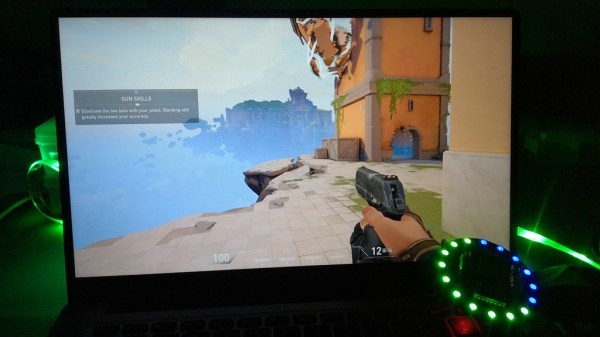
One Bit CPU Runs At A Blistering 60Hz

If you really think hard about it, a CPU is just a very general-purpose state machine. Well, most CPUs are, anyway. The MC14500 is a one-bit computer that has only 16 instructions and was meant to serve in simple tasks where a big CPU wouldn’t work for space, power, or budget reasons. However, [Laughton] took the idea one step further and created a single-bit computer with no real instructions to control a printing press. The finished machine uses a clever format in an EEPROM to drive an endless program.

Honestly, we’d say this is more of a state machine, but we like the idea of it being a minimal CPU which is also true. The design uses the EEPROM in an odd way. Each CPU address really addresses a block of four bytes. The byte that gets processed depends on the current phase and the status of the one-bit flag register.

Continue reading “One Bit CPU Runs At A Blistering 60Hz”

Scratch-Built CO2 Laser Tube Kicks Off A Laser Cutter Build

When we see a CO2 laser cutter build around these parts, chances are pretty good that the focus will be on the mechatronics end, and that the actual laser will be purchased. So when we see a laser cutter project that starts with scratch-building the laser tube, we take notice.

[Cranktown City]’s build style is refreshingly informal, but there’s a lot going on with this build that’s worth looking at — although it’s perhaps best to ignore the sourcing of glass tubing by cutting the ends off of an old fluorescent tube; there’s no mention of what became of the mercury vapor or liquid therein, but we’ll just assume it was disposed of safely. We’ll further assume that stealing nitrogen for the lasing gas mix from car tires was just prank, but we did like the rough-and-ready volumetric method for estimating the gas mix.

The video below shows the whole process of building and testing the tube. Initial tests were disappointing, but with a lot of tweaking and the addition of a much bigger neon sign transformer to power the tube, the familiar bluish-purple plasma made an appearance. Further fiddling with the mirrors revealed the least little bit of laser output — nowhere near enough to start cutting, but certainly on the path to the ultimate goal of building a laser cutter.

We appreciate [Cranktown City]’s unique approach to his builds; you may recall his abuse-powered drill bit index that we recently covered. We’re interested to see where this laser build goes, and we’ll be sure to keep you posted.

Continue reading “Scratch-Built CO2 Laser Tube Kicks Off A Laser Cutter Build”

Classic Triumph Gets A Modern Digital Dash

Analog gauges gave way to all manner of fancy electroluminescent and LED gauges in the ’80s, but the trend didn’t last long. It’s only in the last decade or so that LCD digital gauges have really started to take off in premium cars. [Josh] is putting a modern engine and drivetrain into his classic Triumph GT6, and realised that he’d have to scrap the classic mechanical gauge setup. After not falling in love with anything off the shelf, he decided to whip up his own solution from scratch.

The heart of the build is a Raspberry Pi 4, which interfaces with the car’s modern aftermarket ECU via CANBUS thanks to the PiCAN3 add-on board. Analog sensors, such as those for oil pressure and coolant temperature, are interfaced with a Teensy 4.0 microcontroller which has the analog to digital converters necessary to do the job. Display is via a 12.3″ super-wide LCD sourced off Aliexpress, with the graphics generated by custom PixiJS code running in Chromium under X.

The result is comparable with digital displays in many other modern automobiles, speaking to [Josh]’s abilities not just as a programmer but a graphic designer, too. As a bonus, if he gets sick of the design, it’s trivial to change the graphics without having to dig into the car’s actual hardware.

Gauge upgrades are common on restomod projects; another route taken is to convert classical mechanical gauges to electronic drive. If you’re cooking up your own sweet set of gauges in the garage, be sure to drop us a line! Video after the break.

Continue reading “Classic Triumph Gets A Modern Digital Dash”

Spinning Up A Water Cooled 3D Printed Stirling Engine

The Stirling external combustion engine has fascinated gear heads since its inception, and while the technology has never enjoyed widespread commercialization, there’s a vibrant community of tinkerers who build and test their own takes on the idea. [Leo Fernekes] has been working on a small Stirling engine made from 3D printed parts and common hardware components, and in his latest video he walks viewers through the design and testing process.

We’ve seen Stirling engines with 3D printed parts before, but in most cases, they are just structural components. This time, [Leo] really wanted to push what could be done with plastic parts, so everything from the water jacket for the cold side of the cylinder to the gears and connecting rods of the rhombic drive has been printed. Beyond the bearings and rods, the most notable non-printed component is the stainless steel spice shaker that’s being used as the cylinder.

The piston is made of constrained steel wool.

Mating the hot metal cylinder to the 3D printed parts naturally introduced some problems. The solution [Leo] came up with was to design a toothed collar to hold the cylinder, which reduces the surface area that’s in direct contact. He then used a piece of empty SMD component feed tape as a insulator between the two components, and covered the whole joint in high-temperature silicone.

Like many homebrew Stirling engines, this one isn’t perfect. It vibrates too much, some of the internal components have a tendency to melt during extended runs, and in general, it needs some fine tuning. But it runs, and in the end, that’s really the most important thing with a project like this. Improvements will come with time, especially once [Leo] finishes building the dynamometer he hopes will give him some solid data on how the engine’s overall performance is impacted as he makes changes.

If you’ve got a glass test tube laying around, putting together a basic Stirling engine demonstration is probably a lot easier than you might think. Commercial kits are also available if you’re looking for something more substantial, but even those can benefit from some aftermarket modifications. With a little effort, you’ll have a power plant ready for the surface of Mars in no time.

Continue reading “Spinning Up A Water Cooled 3D Printed Stirling Engine”

Direct Memory Access: Data Transfer Without Micro-Management

In the most simple computer system architecture, all control lies with the CPU (Central Processing Unit). This means not only the execution of commands that affect the CPU’s internal register or cache state, but also the transferring of any bytes from memory to to devices, such as storage and interfaces like serial, USB or Ethernet ports. This approach is called ‘Programmed Input/Output’, or PIO, and was used extensively into the early 1990s for for example PATA storage devices, including ATA-1, ATA-2 and CompactFlash.

Obviously, if the CPU has to handle each memory transfer, this begins to impact system performance significantly. For each memory transfer request, the CPU has to interrupt other work it was doing, set up the transfer and execute it, and restore its previous state before it can continue. As storage and external interfaces began to get faster and faster, this became less acceptable. Instead of PIO taking up a few percent of the CPU’s cycles, a big transfer could take up most cycles, making the system grind to a halt until the transfer completed.

DMA (Direct Memory Access) frees the CPU from these menial tasks. With DMA, peripheral devices do not have to ask the CPU to fetch some data for them, but can do it themselves. Unfortunately, this means multiple systems vying for the same memory pool’s content, which can cause problems. So let’s look at how DMA works, with an eye to figuring out how it can work for us.
Continue reading “Direct Memory Access: Data Transfer Without Micro-Management”

Scanimate Analog Video Synths Produced Oceans Of Motion Graphics

Why doesn’t this kind of stuff ever happen to us? One lucky day back in high school, [Dave Sieg] stumbled upon a room full of new equipment and a guy standing there scratching his head. [Dave]’s curiosity about this fledgling television studio was rewarded when that guy asked [Dave] if he wanted to help set it up. From that point on, [Dave] had the video bug. The rest is analog television history.

Today, [Dave] is the proud owner and maintainer of two Scanimate machines — the first R&D prototype, and the last one of only eight ever produced. The Scanimate is essentially an analog synthesizer for video signals, and they made it possible to move words and pictures around on a screen much more easily than ever before. Any animated logo or graphics seen on TV from the mid-1970s to the mid-80s was likely done with one of these huge machines, and we would jump quite high at the chance to fiddle with one of them.

Analog television signals were continuously variable, and much like an analog music synthesizer, the changes imposed on the signal are immediately discernible. In the first video below, [Dave] introduces the Scanimate and plays around with the Viceland logo a bit.

Stick around for the second and third videos where he superimposes the Scanimate’s output on to the video he’s making, all the while twiddling knobs to add oscillators and thoroughly explaining what’s going on. If you’ve ever played around with Lissajous patterns on an oscilloscope, you’ll really have a feel for what’s happening here. In the fourth video, [Dave] dives deeper and dissects the analog circuits that make up this fantastic piece of equipment.

Here’s another way to play with scan lines: delay the output to some of them and you have a simple scrambler.

Continue reading “Scanimate Analog Video Synths Produced Oceans Of Motion Graphics”