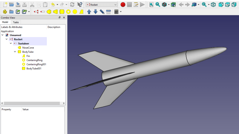
Here’s how FreeCAD works: the program’s design space is separated into different “workbenches”, each of which is intended for a particular set of operations, and a piece of work can be moved between them as needed. There is a sketching workbench, a part design workbench, and now a Rocket workbench has been added to the healthy ecosystem of FreeCAD add-ons. There’s even a series of video tutorials; ain’t open source grand?
It all started when [concretedog] posted on the FreeCAD forums, making a strong case for a Rocket-themed workbench. People got interested, and a short while later [DavesRocketShop] had some useful tools up and running. Here’s a blog post by [concretedog] which goes into detail and background, and while the Rocket workbench is available via FreeCAD’s add-on manager, the very latest experimental builds are available for manual installation on [Dave]’s GitHub repository.
This sort of development and utility is exactly the kind of thing our own Elliot Williams was describing when he made the point that one of open source’s greatest strengths is in the little things, like the FreeCAD ecosystem letting people scratch strange and specific itches, and the ability to share those solutions with others.


Looking forward to the brain surgery workbench.
https://www.youtube.com/watch?v=THNPmhBl-8I
I first read Stine’s “The Model Rocketry Handbook” sometime around about 1970. I hope this addition to the toolbox 50 years later helps today’s enthusiasts stretch their imaginations as much as that volume did mine.
Fabulous book and still very relevant!
I got my start finding that book in my local library in the mid-70s! It led me to this :)
Now if I could only annotate a dimension that doesn’t look out of The Cabinet of Doctor Caligari… that would be nice.
I wish they would work on improving the base UI, and the CAM portion
The Path/CAM workkbench has had an astonishing amount of development, probably the most dev of any single workbench in the last year.
Still the UI is kaka. I can’t use FreeCAD because the color scheme is inconsistent, color inversion doesn’t help and everything is just a mess. So I’m stuck with Fusion360 that has decent UI and is easier to use.
FreeCAD is another example of the Curse of OpenSource UI. Most OpenSource software suffers from interface designed by programmers for programmers. And the more niche is the software, the worse UI is. At least some major packages, like GIMP, LibreOffice, LMMS have decency of copying the existing commercial software UI, which works better…
Also most programmers and designers forgot, what contrast is. Both in OpenSource and in commercial products. For someone who is visually impaired reading a light gray font on white background is practically impossible…
Yes!!! I,m half blind and often find myself looking at empty pages that my wife can read just fine.
When was your last time using FreeCAD? It is highly customizable and out of the box you can choose between different color schemes.
Not saying it comes near Solidworks, Inventor or SolidEdge (which I use frequently for my job, but mostly Solidworks), but it has come a loooong way. I can especially recommend RealThunders Assembly3-Version: https://github.com/realthunder/FreeCAD_assembly3/releases
He’s super quick to kill bugs, make the UI nicer, add many useful features.
realthunder’s experimental fork has UI improvement and lots more.
https://github.com/realthunder/FreeCAD_assembly3
See https://www.youtube.com/watch?v=6iU0g-X5Z1g for guide on UI tweaks
See more videos from same channel https://www.youtube.com/channel/UC4PIO2pZaFKzI97uumFTNSg/videos for more on added features
Sadly most of realthunder’s work did not make it into FreeCAD 0.19, but hopefully 0.20 will get them in and unify FreeCAD, the current situation with different incompatible assembly forks is confusing to say the least.
It is an improvement no doubt but the system is pretty questionable at the core. The whole notion of workbenches is a little against optimizing and making good ux. What’s the difference between part and part design anybody. Frankly I like solvespaces ui. One idea would be to replace to extend its cad kernel so it could support fillets.
Free cad is kind of usable and it’s awesome that it’s free. I really appreciate the authors doing the effort. But I had to stop try to learn it about four times before I could get much usable work done on it.
The workbenches system is what happend when you iterate and pile up functions, design icons to use those, then it´s cluttered with icons, so you sort them into groups and selectively hide the other groups.
Typically people designing complex software know it so well that they totally loose the intuitive good design rule of an UI. They design UIs like APIs.
Is allways Open Rocker https://openrocket.info/
I second the vote for Open Rocket. The user interface appears quite similar to this workbench, but the software is far more capable; Open Rocket will calculate weight, Cg and Cp, stability, altitude, acceleration, max speed, and has a huge database of rocket parts and commercial motors for sims.
Both me and the workbench author Dave use Openrocket, we agree its fantastic, however the FreeCAD workbench compliments it in that you can directly export parts as 3d meshes for printing or I can move to the Path workbench and add toolpaths to cut bulkhead designs etc.
If only FreeCad was even remotely useable.
I didn’t use FreeCAD for a long time, because I had problems with crashes a few years ago.
Now I installed the latest version it’s absolutely usable for my needs. There are also very nice video tutorials if you want to get started with the workflow. :)
This is also my experience — installed a couple years back and it was buggy/crashy to the point of unusable. Install was a PITA. It seems to be mostly over these growing pains now.
There are still lots of low-hanging obstacles to bump your head on, especially on the CAM/Path side of things, though. If you use defaults, for instance, you end up with a design that’s padded out in the positive-Z direction, and to get it millable with Z=0 as the top face requires understanding more of the internals of Path than you’d probably like (between the model, the copy of the model in Path, and the stock, there are a lot of places you can do the wrong things…). Things like that.
What videos?
I like the videos from “flowwies corner”. But they are in german. His “Grundlagen” (“Basics”) videos really helped me a lot to get started. Maybe the automatic translation works for the not native speaker. He is using also a quite up to date version of FreeCAD.
Here’s the link to his channel:
https://m.youtube.com/channel/UCyGwIx_PzM_zE3FKhZRbygQ
Ja. I also found a couple good video series in French. I’m still on the hunt for more resources for the Englisch speakers in the audience. (I also totally recommend Flowwie if you speak German — does he not also have an English channel?)
So far, in EN, I’ve found this series by [thehardwareguy] that’s looking very promising, but still very much in progress. https://www.youtube.com/channel/UCYoC_z7nsi842rI9hM3LZSg He’s got the right approach (IMO) to modelling, though.
What’s missing in all of them, for me, is where I’m having my most difficulty: the CAM / Paths section. Most of the presentations are focused on the CAD side, and are very happy to just export an STL for the 3D printer and call it a day.
But FreeCAD is also improving rapidly, which is good for experienced users, but tough for the documentation to keep up. Like all the 0.18 videos aren’t really all that good for 0.19, which just came out in the last couple months.
Growing pains, IMO.
@Elliot Williams
Check out Joko Engineering- he’s got over 100 videos on FreeCAD, sadly, seems like only ONE on the CAM portion. It’s really hard to find CAM videos for FreeCAD.
Jaques Favre does some great videos for those wanting to use FreeCAD for horology- clock & watch design, with cycloidal gearing.
I have RealThunder 0.19 fork, and I hope they merge his work already…
I still have yet to figure out what the difference or existence purpose is for some of the workbenches. The UI is not intuitive for me at all- but I came from a decade of Inventor, Solidworks, MasterCAM. It’s like pulling teeth to use- but I desperately want to support the project get to a usable serious state because FOSS is awesome, and I’m tired of seeing Autodesk dominate and restrict.
Part of what annoys me is it’s open source so you would think there would be much more public documentation available on the thing because let’s face it people do not want to spend days reading Wiki’s to learn how something works it’s a lot quicker to watch a video and learn from someone using the interface and I think that’s where a lot of things like this suffer.
Anyway- hope the youtuber suggestions help some
FreeCad is significantly more stable today than it was several years ago. And, as others have noted, PathWB has seen a lot of improvements, over that timeframe, as Russ has worked to add to previous work by Brad and Marcus. Sliptonic has a number of English language tutorial videos.
As for colors, workbenches, etc…, the Software is customizable. Including removing WB that are not of interest. And, there is some overlap between several WB—Part, PartDesign, Draft. BTW, the fundamental difference between Part and PartDesign is that PartDesign creates a single part, and Part generally does not. Mostly though, it is work flow preferences.
A significant source of trouble historically has been indexing faces changing with “helper” functions like Fillet, and Chamfer. The issue occurs with these because they are placed on a specific face, and then the face indices change due to some action that adds or subtracts from that list.
Other issues often seen are frustrating, but at root are correct. For example, some actions cannot actually be completed while leaving the model intact. For example, you can specify a 1mm Chamfer on a 0.8mm face, but it cannot work.
Another common issue is that specifying an exact value can cause problems because internal code uses a > rather than >= so you need just under the set resolution to work.
Further, the helper functions for mapping sketches to faces can suffer the same face index issue. But, placing absolute coordinates is completely stable because it is not dependent on a face index. One workaround is to use helper functions to determine a coordinate, then change to an absolute coordinate.
I should point out that FreeCad sits on top of Open Cascade code, and it inherited these issues. RealThunder has reworked much of that, making his branch significantly more stable.
Also, the PathWB 3D additions that Russ has provided use to sit on older freeware, and he has done a good job providing access to it from the GUI. PathWB is increasingly more capable, but it does involve modifying default settings in many cases to achieve the full benefits of the software. It is after all intended to perform complex machining operations, so users do have to learn the software. It’s not solitaire, so not simple to say here’s my model, now machine it. You have to assign tools to a job, and tool controllers to specify speeds and feeds. You have to use various operations to perform cuts. There are modifiers to ops to set ramp entry or dogbones, or to leave cutaways to ensure the work remains fixed.
Whenever I open the rocket workbench freecad crashes