I was having a chat recently with someone, and it surprised me that she had an amateur radio license. I suppose it shouldn’t have come as much of a surprise; after all, getting a ham radio license is a pretty common rite of passage in the life of a hardware hacker. I guess it surprised me because she’d never mentioned it in our past conversations, and as we talked about it, I learned why. “I got my license because I thought ham radio was about building radios, ” she said. “But it’s not.”
In a lot of ways, she is right about the state of ham radio. There was a time that building one’s own gear was as central to the hobby as getting on the air, and perhaps more so. Now, though, with radios as cheap as $30 and the whiz-bang gear that can make reaching out across the planet trivially easy, building your own radios has slipped down a few notches. But homebrewing is far from a dead art, and as we’ll see in this installment of “The $50 Ham”, a WSPR beacon for the HF bands is actually a fun and simple — and cheap — way for the homebrew-curious to get a taste of what it’s like to build your own transmitter.
A Minimalist Approach
In the last $50 Ham installment, I talked about how the Weak Signal Propagation Mode, or WSPR, is used to explore propagation conditions across the world. The concept is simple: a transceiver connected to a WSPR client program, such as the one built into WSJT-X, listens for the FSK-modulated signals that are being transmitted by other stations. The low-bit-rate signals encode a minimal message — the transmitting station’s callsign, Maidenhead grid location, and the transmit power — into a digital signal that takes nearly two full minutes to send. The receiving station then reports the decoded message to a central WSPR database, which keeps track of the contacts and can display a map of paths between stations.
On the receiving end, most of the magic of WSPR lies in the software, particularly in the digital signal processing that pulls data from the oftentimes weak and degraded signal. But the transmitting side is another story; there, the software needed to encode the minimal message is pretty simple, so simple that not much more than a microcontroller is needed to do the job. Really, all that’s needed is an oscillator capable of generating a signal at a fixed frequency, and varying that frequency under software control to encode the message.
There are a lot of ways to go about this, including using the GPIO pins on a Raspberry Pi to generate the RF signal directly. In this case, though, I decided to follow the lead of a lot of other hams and use an Si5351 clock generator breakout board and an Arduino Nano. The clock generator board sports a three-channel PLL-controlled oscillator that talks I2C and has a well-supported library, making it easy to implement a simple oscillator for just about any band.
I decided to make my WSPR beacon for the 20-meter band, for no real reason other than I’ve always had good luck making WSPR contacts on that band during the daylight hours, which is when I spend the most time in my shack. I also decided that for at least my first pass at this project, I’d strip out all the bells and whistles that are so easy to add to an Arduino project. WSPR transmissions need to be carefully synchronized to start at the top of every even-numbered minute, so many of these projects include elaborations such as a GPS receiver or an NTP client to take care of timing. I figured it would be a lot quicker and easier for me to simply watch the clock and press a button to start the WSPR transmission cycle at the proper time.
To that end, I searched for “minimal WSPR transmitters” and found a number of designs that would work for me, including this one by Peter B. Marks. He adapted the code from Jason Milldrum’s (NT7S) examples in his excellent Etherkit library for the Si5351 — we all borrow from each other. My only addition to the code is support for a button to kick off the transmitter. The code simply takes my callsign, grid square, and transmit power, encodes it into a WSPR message, and tells the Si5351 to send the sequence of four different FSK tones that make up the 162-symbol-long message.
/*
* Minimal WSPR beacon using Si5351Arduino library
*
* Based on code:
* Copyright (C) 2015 - 2016 Jason Milldrum
*
*
* This program is free software: you can redistribute it and/or modify
* it under the terms of the GNU General Public License as published by
* the Free Software Foundation, either version 3 of the License, or
* (at your option) any later version.
*
* This program is distributed in the hope that it will be useful,
* but WITHOUT ANY WARRANTY; without even the implied warranty of
* MERCHANTABILITY or FITNESS FOR A PARTICULAR PURPOSE. See the
* GNU General Public License for more details.
*
* You should have received a copy of the GNU General Public License
* along with this program. If not, see
* https://gist.github.com/NT7S/2b5555aa28622c1b3fcbc4d7c74ad926.
*/
#include "Arduino.h"
#include "si5351.h"
#include "Wire.h"
#define TONE_SPACING 146          // ~1.46 Hz
#define WSPR_CTC 10672            // CTC value for WSPR
#define SYMBOL_COUNT WSPR_SYMBOL_COUNT
#define CORRECTION 94674          // Determined experimentally -- parts per billion?
#define INPUT_PIN 7               // pushbutton
#define TX_LED_PIN 13

Si5351 si5351;
JTEncode jtencode;

unsigned long freq = 14097100UL;  // Transmit frequency
char call[7] = "N7DPM";           // Callsign
char loc[5] = "DN17";             // Grid square
uint8_t dbm = 10;                 // Transmit power
uint8_t tx_buffer[SYMBOL_COUNT];
int val = 0;

// Global variables used in ISRs
volatile bool proceed = false;

// Timer interrupt vector. This toggles the variable we use to gate
// each column of output to ensure accurate timing. Called whenever
// Timer1 hits the count set below in setup().
ISR(TIMER1_COMPA_vect)
{
    proceed = true;
    // Serial.println("timer fired");
}

// Loop through the string, transmitting one character at a time.
void encode()
{
    uint8_t i;
    Serial.println("encode()");
    jtencode.wspr_encode(call, loc, dbm, tx_buffer);

    // Reset the tone to 0 and turn on the output
    si5351.set_clock_pwr(SI5351_CLK0, 1);
    digitalWrite(TX_LED_PIN, HIGH);

    // Now do the rest of the message
    for (i = 0; i < SYMBOL_COUNT; i++)
    {
        uint64_t frequency = (freq * 100) + (tx_buffer[i] * TONE_SPACING);
        si5351.set_freq(frequency, SI5351_CLK0);
        Serial.print("freq = ");
        Serial.println(tx_buffer[i]);
        proceed = false;
        while (!proceed);
    }
    Serial.println("message done");
    // Turn off the output
    si5351.set_clock_pwr(SI5351_CLK0, 0);
    digitalWrite(TX_LED_PIN, LOW);
}

void setup()
{
    Serial.begin(115200);
    Serial.println("setup");

    // Use the Arduino's on-board LED as a keying indicator.
    pinMode(TX_LED_PIN, OUTPUT);
    digitalWrite(TX_LED_PIN, LOW);

    // Initialize the Si5351
    // Change the 2nd parameter in init if using a ref osc other
    // than 25 MHz
    si5351.init(SI5351_CRYSTAL_LOAD_8PF, 0, CORRECTION);

    // Set CLK0 output
    si5351.set_freq(freq * 100, SI5351_CLK0);
    si5351.drive_strength(SI5351_CLK0, SI5351_DRIVE_8MA); // Set for max power
    si5351.set_clock_pwr(SI5351_CLK0, 0);                 // Disable the clock initially

    // Set up Timer1 for interrupts every symbol period.
    noInterrupts(); // Turn off interrupts.
    TCCR1A = 0;     // Set entire TCCR1A register to 0; disconnects
    // interrupt output pins, sets normal waveform
    // mode. We're just using Timer1 as a counter.
    TCNT1 = 0;                     // Initialize counter value to 0.
    TCCR1B = (1 << CS12) | // Set CS12 and CS10 bit to set prescale
             (1 << CS10) | // to /1024
             (1 << WGM12); // turn on CTC
    // which gives, 64 us ticks
    TIMSK1 = (1 << OCIE1A); // Enable timer compare interrupt.
    OCR1A = WSPR_CTC;               // Set up interrupt trigger count;
    interrupts();                   // Re-enable interrupts.

    pinMode(INPUT_PIN, INPUT);
}

// wait for button press at the top of any even-numbered minute
void loop()
{
    val = digitalRead(INPUT_PIN);
    if (val == LOW)
    {
        encode(); // transmit once and stop
    }
}
Cleaning Up the Signal
Like any good ham, I tested my tiny transmitter before putting it on the air. The simple dummy load I built back near the beginning of this series came in hand for that, since I was able to hook it up directly to the SMA connector on the breakout board. I connected my oscilloscope to the output and fired up the code. The Si5351 is supposed to generate a square wave; it ended up looking more like a sawtooth wave, but either way, the signal was loaded with harmonics and would need to be cleaned up before going on the air.
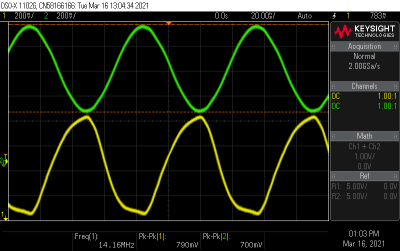
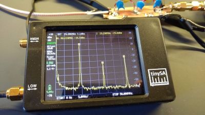
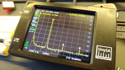
Luckily, low-pass filters that take care of this important bit of spectral hygiene are pretty simple. You can buy them, but this is all about homebrewing, so I spun up a Charlie Morris (ZL2CTM) video on filter design, ran through his math, and came up with values for the capacitors and inductors needed for a filter that cuts off everything above about 14.2 MHz. I used this toroid calculator to figure out how to wind the coils, soldered everything up on a scrap of PCB that had pads cut into it using a cheap plug-cutter bit from Harbor Freight, and tested it using my NanoSA spectrum analyzer.
Having never built a filter like this before, I was surprised how well it did cleaning up the harmonics. The waveform on the scope was a nice, smooth sine wave, and the spectrum analyzer showed a marked decrease in harmonics. The second harmonic, which at 42 MHz is well up into the VHF band, was attenuated by 35 dBm. That’s exactly the kind of spurious a responsible ham wouldn’t want to be spewing around, so I’m glad I built the filter.
On the Air – Sort Of
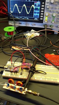
Once I was confident that my little transmitter was putting out a clean signal, I checked to make sure it was putting out signal that was both on-frequency and properly encoded. The Si5351 dev board isn’t exactly a lab-quality signal source — while it holds the set frequency pretty well, it may or may not output the programmed frequency. So the board needs to be calibrated, which is normally a simple matter of tweaking a correction factor in code while monitoring the output on a frequency counter. Sadly, there’s no “NanoFrequencyCounter” in my tiny test suite — yet — so I had to get creative.
My approach was to tune my HF rig to the desired frequency of the WSPR transmitter — 14.097100 MHz — and slowly adjust the transmitter’s frequency while transmitting into a dummy load. This produces an audible beat frequency which pretty much disappears when the two frequencies match. I wasn’t able to completely eliminate the beat frequency, but I did get it down to a couple of Hertz, which I considered close enough.
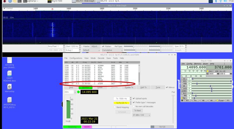
I next checked for a decodable signal by firing up WSJT-X and “broadcasting” to my HF rig. Even with the dummy load connected, I was getting a very strong signal on the waterfall display, and could clearly see the FSK-modulated signal. And I was very pleased to see that WSJT-X cleanly decoded my message.
Better Luck Next Time
Encouraged by these successes, and knowing that plenty of people have made transcontinental WSPR contacts with less power than the 13 mW my little beacon was putting out, I tried getting on the air for real. I hooked the beacon up to my end-fed half-wave antenna and pushed the send button at the appointed time. Sadly, though, I was never able to get any other station to decode my signal. I’ve tried dozens, perhaps hundreds, of times in the last week or so, but I don’t appear to be getting through.
I know my signal is properly encoded, and I know I’m on frequency, so I’m pretty sure the problem is either my antenna or my low-power signal. Given the nature of this series, I’m more inclined to address the latter with a simple power amplifier build. I’ve got a couple of designs in mind for that and I’ve ordered some parts, so we’ll look at that in the next installment and see if I can unlock this particular achievement.




Cool Dan – a really nice and enjoyable write up! I too have played around with the arduino / si5351 – hacking my own software together to make it play, but I ended up taking a short cut on the filter by buying a filter kit for a couple of bucks from qrp-labs.com. Now you’ve inspired me to try making the filter from scratch too. Also if you want to run a bit more power it’s not too hard to put together an amplifier using the BS-170 and a couple of passive parts to up the power to around a watt or so if you want to see many stations from all parts of the world picking you up every day. 73’s Setho
QRP-Labs has inexpensive HF power amp kits, 5W, 10W, 50W. Another source is Kits & Parts:
https://kitsandparts.com/rftoolkits.php
Yes, as @Seth says for the power amplifier use a few BS170 N-channel enhancement mode MOSFETs in parallel just like they are used on the QRP-Labs Ultimate3S QRSS/WSPR transmitter kit. Download the schematic at [1].
WSPR really needs a clean, accurate signal. You should GPS discipline your Si5351. There’s more on the QRP-Labs site about this (they have kits), or do a web search for something like Si5351 GPS Arduino. Here’s a page with a link to an ARRL QEX article: “Si5351 Arduino Controlled GPS Corrected VFO” [2]. The article download is free.
Or just buy the $33 QRP-Labs Ultimate3S QRSS/WSPR transmitter kit [1] and add their $23 QLG2 GPS receiver [3]. But now the $56 total exceeds your $50 limit ;-)
* References:
1. Ultimate3S QRSS/WSPR Transmitter Kit
https://qrp-labs.com/ultimate3/u3s.html
2. Si5351 Arduino Controlled GPS Corrected VFO
http://knology.net/~gmarcus/Si5351.html
3. QLG2 GPS Receiver
https://qrp-labs.com/qlg2.html
Oh and one more thing for even more fun – it’s pretty easy to also connect a cheap GPS board to obtain the time easily and if it has a 1 PPS output even be able to know with a little Arduino software trickery the exact frequency that your Si5351 is transmitting on. (hint – the si5351 has 3 independent outputs all driven from the same internal reference) – Setho
I have a 20 meter hamstick style antenna that I put on my car. That antenna works great, and one nice part is that I can drive it up to local parks that have great look-outs and operate from there. Maybe you could try some sort of compromised vertical like that at some local high-point.
I use an esp8266 and grab the current time from an NTP server for time sync.
73
I suspect your timing is off. WSPR TX needs a good time source for starting the message. As suggested above, using a GPS to get the time correct is the best approach.
There are a number of balloon trackers that xmit WSPR that work well. I have one in the backyard that connects to a random length of wire drapped over tree branches. It’s been received in Hawaii and I’m in Houston.
I always thought amateur radio wasn’t primarily about building transmitters (and/or receivers), but building antennas, and evaluating them for radiation efficiency, size, power handling, bandwidth, directivity etc etc.
That’s just how the hobby has been dumbed down. The focus on antenna building is because so much of the actual building has at the very least moved from the magazines and mostly from actually being done. So people can pretend to be builders by throwing up an antenna. Antennas generally require mechanical skill.
In QST in 1964 you couid read about phase locked loops and other schemes for under the noise reception, cutting edge things like parametric amplifiers and high end receiver design. And Sam Harris doing moonbounce, “if your antenna stays up all winter, it’s too small”. Whether or not people built any of it, it wasn’t swept under the rug.
Here in Canada, the “regular” amateur radio licence (Basic, which is equivalent to the General level in the USA) does not permit licensees to build DIY radios like this — you need to have the Advanced licence (held by about one-third of Canadian amateurs, and equivalent to Extra in the USA) to do so.
Takes a bit of the fun out of the tinkering aspect of the amateur radio hobby.
The rules only specify you cannot design/distribute kits, but you are allowed to assemble a kit for the bands your license allows.
New I.C. rules are still lame, but not that lame yet… just make sure a design has a verifiable band-pass filter and you should be fine. The nanoVNA has really changed the hobby in a lot of ways… ;-)
73
VE7NTP
You can assemble a radio from a commercial kit, but you can’t design your own radio and operate it, as the author here has done.
The rule is that Basic licence holders are allowed to “build and operate all station equipment, except for “home-made” transmitters”, and the term “build” is later defined as “limited to the assembly of commercially available transmitter kits of professional design”.
That wording always seemed like misdirection, since you never needed a license to build a receiver or accessories. It defines what you can’t do by what you can.
I think the kit bit was added later, but I’m too lazy to check.
Fifty years ago, the only thing the Advanced gave you was phone on the HF bands. The Amateur gave you everything else, all the bands, all the modes, full power, and building. The test wasn’t hard, but they were technical questions and you had to draw and explain a few schematics.
In 1978 there was a code free license, the digital license, but only good above 220MHz, and intended to get people interested in digital into the hobby. Very few bothered and I think it was dropped before restructuring in 1990, though anyone who passed the test still had privileges, grandfathered up with restructuring.
I never said we should drop the code, or make the test easier. That was mostly external forces wanting a differentt hobby, helped along by leadership who felt numbers more than quality mattered. Somebody, either the DOC or maybe the RAC said “nobody’s building equipment anymore so why test for it?”.
So we have an easy to get license, but no building of transmitters. It’s no wonder people think it’s about talking on the radio. The US is only nominally better, entry level being the technician license in recent decades, so you start with an FM rig on 2M. Fifty years ago the US Technician and General class license had the same test, except for a 5WPM code test for the Technician (which meant operation above 50MHz).
Even this series focuses on getting on the air, rather than exploring a technical hobby.
I use an esp8266 instead of arduino and grab the current time from an NTP server for sync. My code looks almost identical otherwise.
https://www.instructables.com/Getting-Time-From-Internet-Using-ESP8266-NTP-Clock/
Glad you found my code to be useful!
Given your testing of the timing of your transmission in the lab (which as you mention is very critical for a proper decode), I can only assume that you’re correct that you need more output power and perhaps a better antenna. In my experience, end-fed half-wave antenna are a bit of a mixed bag. I think the tried-and-true half-wave dipole is hard to beat. I’ve also found in experimenting with my upcoming OpenBeacon 2 MEPT that a vertical with an elevated radial (at least 2 meters off of the ground) also works well.
Definitely build that DIY amplifier for this project. 10 mW can get out if you have a good antenna and the conditions are right, but it’s tough. You’ll do much better with about 10-15 dB of amplification, which you can easily get with one amp stage. The old QRP classic Class E amp built from 2N7000 or BS170s would be perfect here.
Good luck and 73,
Jason NT7S
Fun!
Like others said, the timing is critical. I’d suggest having the Arduino listen to the serial port and have a little program on your computer watch the clock for you and send a signal to the board to start. (Just make sure your *computer* is in time with a time source.)
Along these lines, I’d suggest looking at this guy’s recent project – I found it very easy to use this to get up and running with my own FT8 setup (could also do wspr but I already have a QCX for that): https://www.reddit.com/r/amateurradio/comments/l9m25l/homebrew_ft8_transceiver/
I got my Ham license, in part, because of inspiration from this series. I am having a bit of trouble figuring out what I want to do with it, though, and Charlie Morton videos make me feel unworthy. This, though, looks exactly like the right thing I could build and transmit with. Thank you, I’ve found my next project.
73,
Kevin AC3HG
I used the NT7S code with an Arduino to make a WSPR beacon for the 630M band (472KHz). I had to change a few numbers to make the Si5351 run at those frequencies.
I was not able to be heard by anyone so I built an amplifier with an IRF710 FET putting out 12W. Practical antennas at those frequencies are very inefficient. I figured mine was about 1% efficient. With other losses I was probably putting out about 0.1 Watt. It was regularly picked up all over the US and frequently in Hawaii from Wisconsin.
http://www.w9xt.com/page_radio_gadgets_630m.html
73
Gary, W9XT
She got licensed because she thought it was about building radios. I didn’t get licensed for many years because I thought building a radio was a requirement.
In the USA, FCC Rules Part 97.203(d)
“A beacon may be automatically controlled while it is transmitting on the 28.20-28.30 MHz, 50.06-50.08 MHz, 144.275-144.300 MHz, 222.05-222.06 MHz or 432.300-432.400 MHz segments, or on the 33 cm and shorter wavelength bands.”
Does this apply or not?
What is the requirement to operate an unmanned Beacon according to the FCC rules ?
Interesting Article, thanks for sharing! I You might be interesting to read about this global WSPR Beacon Project I just kicked-off https://github.com/HB9VQQ/WSPRBeacon
In the US, the FCC requires all non-intended/out-of-band emissions to be kept at least 43 dB below the max power of the main signal. Hence a 35 dB reduction (not 35 dBm since dBm is a power measurement) technically breaks the requirement.
I remember using RPi 3 for WSPR beacon using GPIO and 40m low pass filter shield. This was fed to a half size G5RV via 15 m long coax in a very limiting location (surrounded by higher ground). I’ve been received thousands of times, the furthest receiving station being ~2600 km away.
The point is that RPi produces about 16 mW max on the GPIO pin if my memory serves. So not that much of a difference. I don’t think that power is your issue. Although, if it is the antenna or lossy connection, an amplifier can help overcome this.
Dan. This is a pretty cool article. I have o ly been into WSPR for a few weeks and set up my Icom ic7100 as a becon running 1 watt. Too expensive of a radio for this purpose. However I was very impressed with the massive reception report received around the world. The Arduino with the Si5153 looks like a great alternative to plant it on 20meters to test my home brew mag loop and make it solar/battery operated.
The whole thing can be mounted to thr feed point of the Magloop.
Do I understand one that the Arduino button to start the beacon. The way the article reads this is only a 1shot, and does not repeat. Is that a limitation of the Arduino software, or WSPR etiquette? I was looking to have this fully automated.
Dennis WA6ATI
Dan: just discovered your blog and wanted to say thanks for posting great info like this. I’ve been a ham since I was a teenager and have always enjoyed the different aspects of the hobby. Lately I helped form a sort of neighborhood radio club in a big city and we’ve enjoyed using simplex VHF for a club freq rather than relying on repeaters. Almost everyone of us has improved our antenna system so we could all reach each other. Fun stuff. You can see our progress at Wa5wrl.org.
Thanks again and 73
Rich n5csu
Dan: Just got my license and was trying to decide which facet of the hobby to dive into. Your article described some areas I had been thinking about. It was well written and very helpful. I had been thinking that putting a digital signal generator module onto a antenna might be viable. I now know what I’ll be working on for the next few months.
73
Mark AC1QW