[Mansour Behabadi] wanted to harness the high power capability of USB-C using as simple a hardware design as possible. After some research and experimental prototyping, he designed the fpx — an easy to use USB‑C power delivery board. The fpx is an improved follow up to his earlier USB PD project fabpide2 which we featured some time back. However, practical implementation of the USB PD protocol can be a bed of thorns. Negotiating power delivery usually requires a dedicated PD controller coupled with a micro-controller for user control.
With USB PD, a USB-C port can be configured as either a source, a sink, or both and allows connected devices to negotiate up to 100 W (20 V, 5 A) of power. The fpx is based around the popular STUSB4500 PD controller, which does most of the PD heavy lifting. To program the STUSB4500, he used an ATtiny 816 micro-controller, whose UPDI programming and debugging interface consumes lower board real estate.
However, what’s a little bit different is the way the fpx is programmed — by sending binary black and white flashes from any device that can display a web page. Using light isn’t a particularly new way of programming. We’ve seen it used almost a decade back by WayneAndLayne for their Blinky PoV projects, and later by the Electric Imp’s BlinkUp app. The fpx uses a similar method to read flashes of light from a screen which are picked up by a photo-transistor connected to the ATtiny. The ATtiny then communicates with the STUSB4500 over I2C. This eliminates the requirement for special software or an IDE for programming and doesn’t need any physical cable connection. Check out [Mansour]’s blog post where he walks us through the details of how he managed to wrangle the optical programming challenge.
Many of the commercially available USB PD decoy/detector/trigger boards use either solder jumpers or a switch with an RGB LED to adjust Power Delivery Output (PDO). [Mansour]’s method may be a little more robust and reliable. The STUSB4500 can store two separate PDO values and can negotiate with a source according to its capability. If the source cannot offer either of these options, the fpx can either request for a minimal 5 V / 100 mA setting, or disable the output. The fpx is an open source project, accessible on Github. Check out the video after the break for an overview of the fpx.
Thanks for the tip, [Lacey]


This is exactly what I was looking for, thank you!
i like the optical programming. that is a good hack.
“[Mansour]’s method may be a little more robust and reliable.”
*Mansour has to try 3 times to get it to program in his demo video*
lol, don’t get me wrong, it is super neat, but there is a reason you don’t see it used very often. IMO the better solution is to have jumpers for the popular configs, then have the UPDI line for people that want to get fancy.
Although a fancy solution, it only adds to cost and complexity. some solder bridges would’ve done the same for less.
You can configure this board with two preferences, each allowing you to pick between 5 voltages, and current at 0.5A steps up to 5A. You’ll need quite a few solder bridges for that. And re-configuration will be a nightmare. It’s also impossible to fit them on this footprint. For simpler use-cases I agree, but I wanted to make sure this board (which costs $20) is flexible and easily re-configurable.
4 pads for 16 levels (Binary-Style) of current and 3 pads for 6 Voltages.
Times 2 for 2 configs = 14 pads + one pad for fallback (Open = Disable, closed = 5V100mA).
I doupt there will be enough pins on the chip to read that in. So a parallel-serial-chip is needed. And there is propably more space needed and higher cost than the simple photodiode used here.
With a nice case which you can lay flat on the screen and limits the stray light to a minimum, i am quite sure the programming can be quite reliable and good.
From a strictly engineering view. I’m pretty sure you solved it.
> but there is a reason you don’t see it used very often.
What is the reason?
You can’t just say “there’s a better way” and then explain your better way without explaining why.
I have no idea what a UPDI line is or how to start getting fancy, but I have plenty of project where I’d like to use USB-C instead of Micro-B and this type of solution would work fine for me.
I explained the reason… In the demo to show it off, it didn’t work the first 2 times. There have been commercial examples including wrist watches and kids toys that could be programmed in similar ways, that were all short lived. Ambient light/sun, contrast ratios of various screens, and other problems stack up in ways to make the operation not great.
You are just yankin my chain on not knowing what UPDI is. Everyone on this site knows what UPDI is.
With proper error correction and some auto-gain you can make it reliable enough. But bit-rate is a problem, as without low-level access to the GPU you can’t time frames more accurately than maybe 10 or 20 FPS.
And while I know SWD, I honestly have never heard of UPDI.
It’s a USB device. Why not just program it over USB?
An ATTINY plus a photodiode is cheaper and smaller than an MCU that supports USB.
That’s because it’s not a USB device. It’s a USB power supply.
Careful! If you are wearing your Timex Datalink watch while programming that you might get a shock!
Ahaha, that’s what I was thinking of with this thing. My dad had a Datalink and regularly got annoyed at trying to program it on the CRT monitor he had back in… oh, 1997? There was a lot of beeping from the watch.
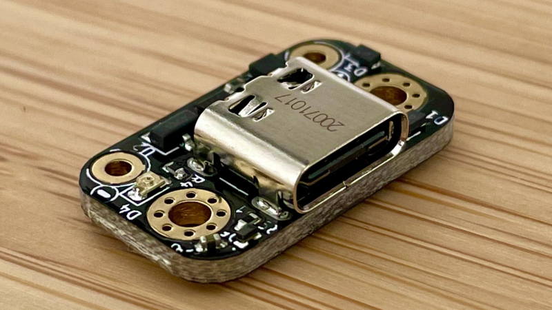
Proper mounting holes! So many DIY parts don’t have them and act like physically mounting a board is some afterthought. Well done.
Also a USB-C connector that uses through hole frame mounting holes. Most of the time I see people complaining about tiny USB connectors failing it’s because of fully SMT connectors (and usually without any vias on the mounting pads to keep them anchored).
A small SMD DIP-switch would have been better..
The photos do not do the size justice. There is no way to put anything mechanical on that board.
wouldn’t it have been easier to use an IR sensor coupled with a universal remote to program it? A list of key input codes would select voltage and current limits. start code + 3 digit voltage, 3 digit current limit + end code
That’s a very interesting alternative and I’ll keep it in mind for the future. Having thought about it for a bit, I would still go with this because of the user experience and availability of IR remotes.
ASK IR is very robust, but there are many, many different protocols out there. Even remotes from the same manufacturer sometimes use different codes for the same button, so without either restricting it to a specific type of remote or having some kind of programming/auto-learn feature you would have no idea what command you just sent.
there are tons of sequences, so as long as you target a specific manufacturer (vizio, samsung, sony, etc) then you can limit to simply input numbers. If it works with your TV then there is a high change it will work. Maybe a little additional LED would bleep bloop if its working!
I see the power out pins, but I did not see the communication lines. Does this only supply power or can you use it to bring in the USB communication lines as well?
Only power
forgot to say that I really like what I see in this design at first glance. I will have to keep this in mind if I need to build/retrofit any powered USB-C devices.
This is totally awesome. I’ll definitely be getting one when I do my next USB powered project!
If you want to expand your product line, I’d love a similar board that could charge different configurations of lipo batteries, that you would configure in a similar fashion
You know, Timex used the output of your monitor to program the datalink watch back in the 90’s and I think even earlier.
https://www.youtube.com/watch?v=64EAfXsX828