Sometimes it’s nice when you can do everything you need to do with just one single port. In this vein, [Nicola Strappazzon] whipped up a circuit to combine serial and UPDI programming in a very convenient way.
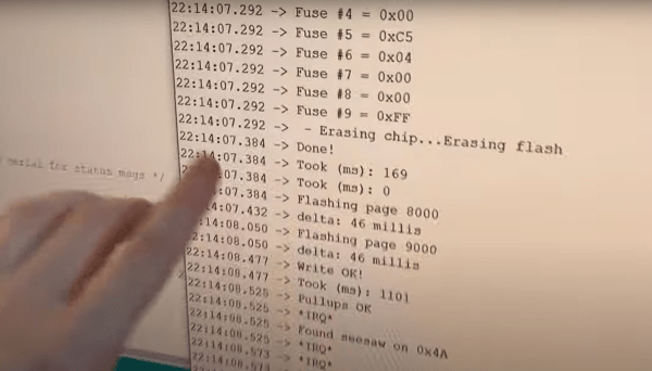
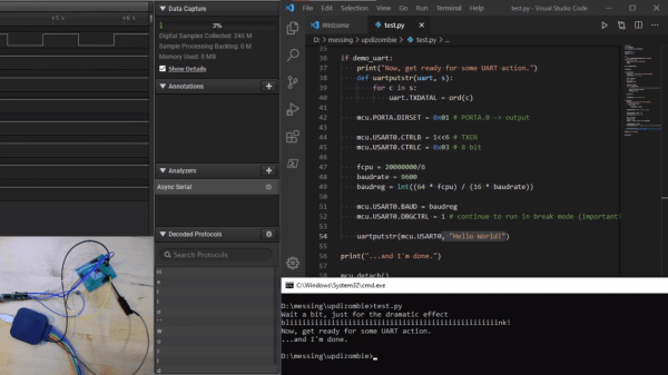
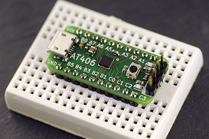
As an example, [Nicola] demonstrates the concept using an AVR128DA28 microcontroller. It’s paired with a 4052 multiplexer IC and a CH340 USB-to-serial chip. Everything is wired up such that the 4052 acts as a switch for the signal coming from the CH340. When the RTS flow-control signal is set high, it switches the 4052 to hook up the CH340’s RX and TX pins to the UDPI interface on the AVR microcontroller. Conversely, when the RTS signal is set low, the CH340 is instead hooked up to the serial UART on the microcontroller. From there, it’s a simple matter of configuring avrdude to properly set the RTS pin when attempting to program the attached device.
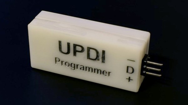
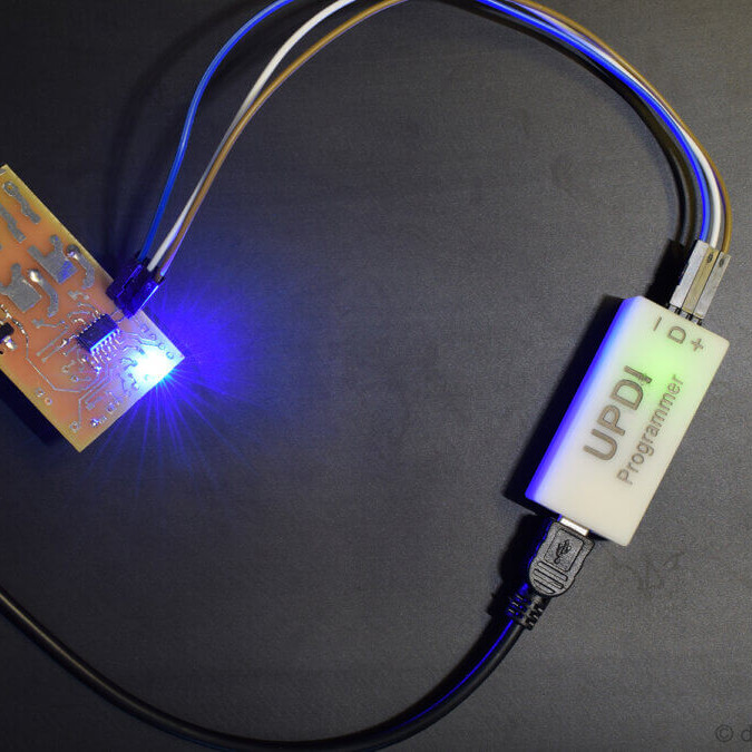
If you’re working with UPDI devices and you want to be able to talk to them and program them with a minimum of fuss, this project might be useful for you. We’ve looked at dedicated UPDI programmers before, too. If you’re cooking up your own nifty microcontroller hacks, don’t hesitate to let us know on the tipsline.
![A Hackaday.io page screenshot, showing all the numerous CH552 projects from [Stefan].](https://hackaday.com/wp-content/uploads/2023/02/hadimg_ch552_projects_feat.png?w=600&h=450)