
In a satisfying blend of classic console restoration and modern modding, [Elliot] from the Retro Future channel has transformed a broken, dirty PlayStation into what they call the “ultimate PS1.”
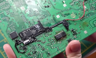
The first step was to deal with the really grungy case. The shell was soaked in dish soap and given a good brushing before being packed and sent to a collaborator. Upon inspection of the internals, several unknown modifications to the PCB were evident. These were likely to support playing home-burned copies of pirated games, as well as an NTSC region hack (for this PAL version of the console), courtesy of a dodgy-looking crystal oscillator hanging on the end of some wires.
Luckily, the PS1 product design is highly modular, giving excellent repairability, which made reversing this a doddle. The mod wiring was removed by simply desoldering it, but the cut traces needed to be cleaned up and reconnected to return it to stock condition.


