A few months ago, a tweet by [Ken Shirriff] asking about simple digital simulators caught my attention. The topic came up again in May when a repair video by [CuriousMarc] featured one such simulator called Logisim-evolution. It made me want to take a fresh look on what’s out there and which features set the different simulators apart.
So today, let’s take a quick survey of a few such simulators that I found. I’m focusing on plain logic simulators, analyzing ones and zeros using Boolean logic. They are not doing SPICE-like analog analysis of transistor logic gates, but they’re still quite handy for proofing out designs.
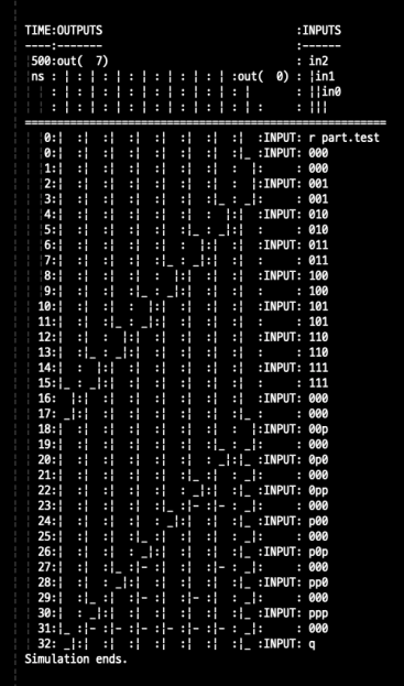
Logicsim
Logicsim from 1983 is the oldest one on our list, developed by Wun Chin Kau and Douglas Jones in support of computer science lab classes at the University of Iowa Computer Science department. It is a text-based simulator, open source for personal and research use, and written in Pascal. As recent as 2008, one user was able to compile it using FreePascal.

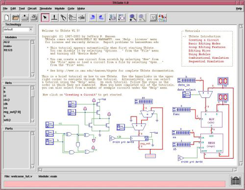
TKGate

Next is TKGate, developed as a project by undergraduates in 1987 at the Carnegie Mellon University. It is written in C and Tcl, last updated in 2016, and maintained by Jeffery Hansen here on Sourceforge. Of all the simulators I found, this is the only one which contains a hidden pancake recipe.
Logisim
The next one is Logisim (note the missing ‘c’), developed by Prof Carl Burch in 2000 for his students at the College of St Benedict and St John’s University in Minnesota. Written in Java, it is open source and is available on Sourceforge. He changed focus in 2013 to develop a follow-on program called Toves, also open source on Sourceforge, but written in C#/Mono. It appears both projects have been abandoned, though are still available. Logisim seems to have been quite popular among colleges and universities
There are a number of forks of Logisim which popped up to fill the void when Prof Burch stepped aside. Among these are:
- Logisim fork by Joseph Lawrance of the Wentworth Institute of Technology, Boston.
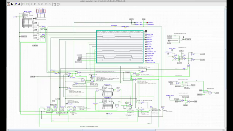
- Logisim-evolution out of the Institute of Reconfigurable & Embedded Digital Systems (REDS), Yverdon-les-Bains Switzerland. UPDATE: Since writing this article, [CuriousMarc] has posted a tutorial video on how to get started with Logisim-evolution.
- Digital, a simulator Inspired by Logisim, but built from scratch by Prof Helmut Neemann in Baden-Württemberg Cooperative State University, Germany
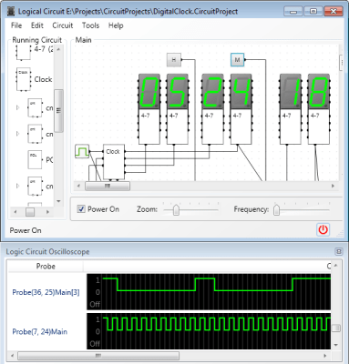
Logic Circuit and a Few Others

Logic Circuit, developed in 2016, is open source written in Visual Studio for Windows.
Missing in action is a program called logic-sim by Richard Reid of Michigan State University. We found this one explained in great detail in a computer science course syllabus at Emory University. Alas, the program itself is either proprietary or lost to internet digital rot.
Here are a few more from the replies to [Ken]’s tweet:
- Chipmunk Open Circuit Design
- Anitra Development Tools
- Labcenter VSM for Proteus
- SmartSim (on Raspberry Pi)
- Antares Digital Circuit Learning Platform
- EDA Playground
- Open Source Quantum Development
- Multisim Live
- Autodesk Tinkercad
- CEDAR Logic Simulator
- Logic.ly
- iCircuit 3D
- Simulator.io
- Circuitverse
- Logic Friday
I was surprised by how many simulators are out there, although I was expecting more text-based command line tools like Logicsim. We’ve written about some of these logic simulators in the past, including the textual LogicEmu and a Javascript TTL Simulator. Do you use any of these simulators in your projects, or can you recommend one? And what’s your take on textual vs GUI interfaces for these tools? Let us know in the comments below.


Logisim is still my go to for testing out my various logic projects.
My vote (after many years of preferring logisim) now goes to Digital, and anything else from https://github.com/hneemann
I was gonna say, Digital is missing from this list and it’s really been helping me a lot lately as I try to build my first 6502 PC.
I looked into it because it has the ability to compile for GALs & output HDL if I need it, plus it lets me work with virtual 74 series ICs instead of just logic gates which is what I was stuck with in the javascript online simulator I was using before.
If possible could you fill me in on using “Digital” to design your own 6502 PC. I am presently planning on having 6 HS students this summer build an 8-bit computer following Ben Eater’s videos on YouTube. Before they build it they must first design it on “Digital”, then draft it on “Fritzing” after which they will actually build it. I’m trying to plan for a following project for them and designing a PC came to mind. It looks logical but being a retired Mechanical Engineer & former HS Math (40 years ago!) I have no idea of where to start. Is “Digital” capable of designing a 6502? Anything you could think of that might help me in this regard would be deeply appreciated. Bob Englert (bobenglert1945@gmail.com)
At work we use LASAR by Teradyne. It’s definitely not an open source program, but is text based. It is able to simulate faults (open to Z, stuck at 0, etc…) and generate a fault dictionary. When you run your patterns on the actual hardware it will automatically diagnose what is wrong based on the fault signature. Very Niche stuff, but alot of repair depots cannot just replace the electronics and need to repair them.
I want to mention LoCAD by Karl-Heinz Loch for a simple logic simulator that runs on an iPad.
https://www.khloch.de/en/locad-fuer-ipad/
I use Profilab for about 25 years now – very happy with it.
Generate exe files that run independantly.
https://www.electronic-software-shop.com/lng/en/electronic-software/profilab-expert-40.html?language=en
There is a lower cost version as wel – digital only
The lower cost version
https://www.electronic-software-shop.com/lng/en/electronic-software/digital-profilab-40.html?language=en
Some years ago I played around with Hades. As far as I know it hasn’t been updated for several years but it’s still available at https://tams.informatik.uni-hamburg.de/applets/hades/webdemos/
Typo note: What should be a link to “Multisim Live,” is actually just a duplicate of the previous link, “Open Source Quantum Development.”
Thanks, fixed.
I have been using the Falstad Circuit Simulator in my teachings for 5 months now, and I’m happy with it. I didn’t try all of the list before, but for sure in Falstad I can simulate the time response of the flip flops. I can’t did that with Logisim and that’s the main reason I switch to. Falstad is open source, run in a browser or can be installed locally as a JS applet.
https://www.falstad.com/circuit/circuitjs.html
+1 !!
circuitjs is far from perfect but in its narrow range, it’s great :-)
I use it a lot.
Came here to post this.
The biggest draw IMO is the ability to “save” circuits as links so someone else can open them and immediately have a working circuit to mess with. No install, no login, just pure functionality.
Mid 90’s we used Electronics Workbench in highschool.
In mid 2020’s we used Electronics Workbench in college…
I got a lot of use out of MultiMedia Logic for Windows in the old days. Looks like it’s still around, and open-source now:
https://sourceforge.net/projects/multimedialogic/
I came here looking for this. I couldn’t remember the name, just the aesthetic. Glad someone else remembers it too!
The most up to date place to get CEDAR Logic is here: https://github.com/CedarvilleCS/CedarLogic
It is currently being maintained by my friend Joe Richardson (we were classmates while studying at Cedarville University).
Although I wouldn’t call LTspice exactly “simple”, LTspice [1] (free, not crippled, closed source), now owned by Analog Devices Inc. (ADI), supports 74xx logic parts (LS and HC families the last time I looked) with some tweakable analog parameters. The libraries and a supporting document on installation and use can be downloaded from the files area of the LTspice groups.io site[2]. Yes, groups.io needs you to login to download files. Alternatively, it is not very difficult to manually build behavioral logic device macro-models and symbols in LTspice. That’s were the existing 74xx libraries came from.
* References:
1. LTspice home at ADI:
http://www.analog.com/LTspice
2. LTspice groups.io site:
https://groups.io/g/LTspice
Hey, awesome! I’d say that very often, you find yourself in a situation where you can write down the logic as *code*, i.e. as specification which gates connect to what.
In that case, you could do that, using a *Hardware Description Language*, and use a simulator on that – very mature idea, and there’s a wealth of tools for it!
Popular is writing *VHDL*, using the *ghdl* tool¹ to simulate that. The intro-level examples² show how to simulate a 100 MHz clock generator!
The simulation can write the output waveform to a file that the *GtkWave* program can display – fancy.
A similar workflow exists for the verilog language, using *Verilator*⁴ if you want to build a simulator that you can run yourself. But many people might be happier with *Icarus Verilog*⁵, which also supports direct simulation to a GtkWave file.
BUT::
Realistically, learning a HDL that is syntactically very 1980s (like VHDL and Verilog, sorry folks) is probably very much for a quick simulation. Enter nmigen⁶: A python-based domain specific language for *exactly* this. The getting started guide⁷ shows how to work it so you get the output of a counter. How low-level you specify that counter (whether you just say “add the two numbers”, or build full adders from half adders from logic gates) is up to you (that’s the beauty of all HDLs).
¹ https://ghdl.readthedocs.io/en/latest/
² https://ghdl.readthedocs.io/en/latest/quick_start/heartbeat/README.html
³ http://gtkwave.sourceforge.net/
⁴ https://en.wikipedia.org/wiki/Verilator
⁵ https://iverilog.fandom.com/wiki/User_Guide
⁶ https://github.com/nmigen/nmigen
⁷ https://nmigen.info/nmigen/latest/start.html
Or you could simply use pencil and paper to optimize your combinational and/or sequential logic design using Boolean Algebra[1] and/or Karnaugh Maps[2].
* References:
1. Boolean Algebra
https://en.wikipedia.org/wiki/Boolean_algebra
2. Karnaugh Maps
https://en.wikipedia.org/wiki/Karnaugh_map
I’d say you’re 100% wrong on verilog being only for a quick simulation. Verilog and VHDL (and things like SystemVerilog) are the standard in industry for giant projects. There is a ton of tool support, logic synthesis support, simulators, hardware accelerators, etc that just doesn’t exist for all these new-fangled python or haskell or whatever based languages/simulators.
http://happylogicsimulator.com/
I design chips for a living, so please take my advice and just use Verilog. If you are teaching a class to kids, I might see how one of these graphical design tools might be useful, but if you are actually building/simulating anything real, graphical design gets too cumbersome too quickly, which is why nobody in the real world uses it. I know it might seem intimidating, but just find a template to start off and then modify it. I haven’t used the freeware tools but I’m sure they are adequate for basic designs and have to be far better than anything in which you make a drawing of gates.
Happy Logic Simulator is very simple and requires no install http://happylogicsimulator.com/
Electra.Academy could be a candidate as well. Digital Logic Simulator with some good features like sharing of circuits. e.g. https://electra.academy/circuit/?shared=fe3fdee8a00c5aa137803b6e30317d8247888d5f
I have a DOS version of the excellenic logic-sim from MSU (the 1991 version), but no documentation.
It was indeed astounding and ahead of its’s time.
it read a line by line description file with devices and how they were connected. The catalog of devices had a small robot and a small elevator simulator as well as a complete computer. It was designed so you could replace each part of the computer with its’s components (CPU to ALU, CPU to memory and Program Counter) all the way down to gates.
In the first week you wrote an assembly language program to make a “robot” bounce around a room (which was shown in vector graphics). The next week you replaced the entire computer with it’s parts and so on.
When you were done it took over 30 minutes to run on a Sparc-3 and you had to demonstrate it week by week.
It was a brilliant piece of code as well as a great educational tool.
There was a DOS and a SUN version and a huge 100 page manual you had to buy a copy of at Kinkos.
I should find the sim.exe of it and see if can be made to be reverse engineered,
Oh, here is some information on Dr Reid’s simulator.
https://dl.acm.org/doi/pdf/10.1145/134510.134549
[Editor note – Link is verified to be a pdf of dr. reid’s paper. -AF]
Here is a pyton based tool (Running on multiple platforms), both in GUI and scripted.
https://github.com/freand76/digsim