One of the hardest, but sometimes best, things you can do for a project is to walk away. [Jroobi] had spent hundreds of hours crafting the digital dash for his MX5 Miata (video, embedded below) and after spending far too long chasing down I2C bugs, he made the difficult decision to step away for a while. However, as of May 2021, [Jroobi] returned to the project and found a power supply was under-specified and was causing brownouts that resulted in crashes.
All in all, it’s an incredible work of engineering. Everything from the massive codebase that describes all the different states to the tasteful graphic design is masterfully done. The Star-Trek-inspired theme and attention to detail really show in the different modes on the tachometer. The dynamic soft RPM limit based on engine temperature is particularly ingenious.
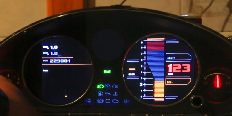
Under the hood of this custom dash are two Ardunios running the show. The center media console offers more controls with a generous touch screen while the instrument cluster shows most of the data. They talk over I2C to each other and communicate with other parts in the car, such as the RGB cabin lighting and the TEIN electronic suspension dampeners. Fuel and temperature levels come in as voltage levels which can be read via an ADC. The gear position is calculated based on RPMs and speed given the wheel size and the transmission in the vehicle.
It is a phenomenal labor of love and if you’re inspired to further upgrade your Miata you might want to see how to put carbs on the engine or RGB light rings in the instruments.


I like it a lot.
Where do I send money
This is the highest wizardry level I have ever seen. Above mine. I’m too lazy so I still stay with ancient CRT displays.
Greatest respect!
Where can I get one for my Miata
Very 80’s!
https://www.youtube.com/watch?v=mTLCbBYAt9E
I really wouldn’t use some Arduino with a janky power supply to power up my speedometer. There is a reason why these things are built to safety standards – https://en.wikipedia.org/wiki/Automotive_Safety_Integrity_Level
Really curious if this would make it past an MOT.
I wouldn’t touch he Arduino because they neuter hardware debugger support. One could come in handy at least for post mortem getting some hints about the cause of a crash. In this case, the brown out flag might have been set. Trace the flow with break points, examine the hardware registers or global variable etc. These are the things that your printf won’t tell you – that is without you having to recompile in and may alter the timing of the code enough to have issue.
There is also about making things more complicated by having 2 uC in the design.
Power supply for automotive have to handle all kinds of nasty stuff without blowing up or crashing e.g. electrical noises, spikes, being able to tolerate negative voltage (someone jumpstart with wrong polarity), overvoltage, under-voltage etc.
If losing the functionality of the gauge cluster on a car that has absolutely no drivers aids and not a single function of the car is controlled by is going to cause you to crash your car… Maybe you should stick to a bicycle or riding the bus.
Haven’t read the article — my understanding is that this is more or less an ECU cluster replacement
It’s not a “If losing the…”, all dash panel are built with security and failure control. If you need to light a failure (eg ABS or ESP or engine fault) then you must be sure it is displayed, otherwise it’s a liability. Same with displayed speed. It’s must be at least over the value, not fixed to 42 when in reality you are at 69.
Most manufacturer (in fact ODM/OEM) use OS like GreenHills, and follow strict process and norm (misra, aspice, iso26262), and even with it they fails regularly (looking at you Toy…)
A speedometer in particular isn’t particularly important from an up-time perspective. If it dies, the car can still otherwise function. The fear would be if it somehow started lying and reporting speeds slower than actual. There’s nothing particular about Arduino that would make that more or less likely, other than perhaps the possibility of a counterfeit MCU. If it’s tapped into a CAN bus, then perhaps it could mess something up, but you’re not going to get into too much trouble plugging into an OBD2 port.
I’m more worried about the “security alarms” poorly spliced into the ignition harnesses of most cars going through dealerships these days.
Pfff. I drove my old 75 Camaro for years with no working speedometer. The little gearbox in the cable (because the car had a non-standard differential ratio) kept seizing up and wringing the end off the cable. I got tired of buying new cables.
Hehehe I do the same with my citrohen Mehari 71. and pass MOT-equivalent test in Argentina.
Of course it can pass an MOT. Speedometer isn’t even a test item, although they should fail you if they notice it not working. Last MOT the only things working on my kit car dashboard were the indicator lights for full beam and fog light (test items) and the water temperature gauge. More of it works now. On a good day anyway.
The only safety critical things on dashboards tend to be the warning lights for safety critical items. On a modern car stuff like ABS, stability control and airbags should be able to tell you if they’re not working or bad things can happen. These are normally independent of the gauge cluster though.
Jroobi here, I’ve got several arduinos in my car running if filtered 12v rails perfectly fine and stable for the last 8 years. I’d used a bodgy 12v “2amp” mains transformer which wasn’t even pushing out 400mA. Of all the things tested, I’d overlooked this. But have addressed that now. 👍
I think this is the most updated one and it’s very cool!
Very nice job, to a point where that kinda cant be the only thing changed on the car anymore, that miata needs more sci-fi related mods now, with this sort of attention to detail :)
“May 2021, [Jroobi] returned to the project and found a power supply was under-specified and was causing brownouts that resulted in crashes.”
None fatal I hope!
B^)
Ooo. The design is pretty neat. And the star trek sounds on the touch screen.
The only thing is it really needs something more powerful running it, the lag and update rate is awful. He should try one of the higher end Teensy’s or something.
Hope he has some good power supply filtering, i designed a one off board for a friend to control lighting in a corvette. Worked great till he hit the horn, then lights would come on. The RFI from the horn just permeated the system freaking out the uC. Tried filtering, couldnt get it to go away.
The Arduino Dues are the only Arduino I can use to run the screens AND get the gpio numbers needed while keeping the code as simple to work with as possible. (It’s not simple in its current state!). I know a teensy can drive one of the screens but there’s too few gpio pins left. I’ve also reinvented this so many times I’m kinda sick of starting from scratch with a new Dev board and drawing PCBs for it etc. I’ll try to go into more detail of the choices and reasons why it’s the way ive done it. I promise there are many valid reasons and design choices chosen for the path I’ve taken with it. No Doubt there are better ones, but am learning alone and doing other things with my time too.
I think what he has done is amazing. Is it a Hack? – Sure.
What Can the Hack-A-day Community Learn from this. Nearly nothing – He shares literally zero info apart from it has arduino’s somewhere in it.
nothing on how it’s build.
What Arduino’s he used- Nope
What Screens he used – Nope
How he even Mounted anything – Nope
Even a hint how he’s communicating with the car – nope.
Gui Library’s – nope
Just a show off video – yep
I come to Hack-a-day for the community of like Minded Open Source or assistive Articles and general creative shared idea’s.
Cool Project to be sure. I guess it’s just me. I held Hack-a-day to higher standard
Of Praising those who share with others by helping them get recognition through the Major traffic hack-a-day offers.
Perhaps it just wishful thinking on my part. I always praised Hack-a-day as a Help us Help you.
This Highlight just leaves me disappointed.
Have posted pretty much all the info you say I haven’t. It’s all in replies to comments or in the video descriptions bit it’s there. Pretty much the same way I learnt to do this, not from the original questions but from the responses to them in forums, other YouTube videos and a huge amount of digging around etc. I’ve stated which libraries, which LCDs I’ve used for the touch screen, and what shields I’ve used, and where ive bought (eventually developing my own) I’ve only got a handful of videos done on this and the info is in the comments. Arduino dues (as mentioned in the YouTube links) , 7″ cpld TFT touchscreens, ghlawrence UTFT libraries. It’s not hard to dig into to find out more, but one thing is certain, the coding is hard, messy and detailed. 👍 Jroobi
Cool. Maybe you can post what the round displays are. I don’t see that info anywhere.
Because the display s aren’t round. If you look a bit closer you can see that the screens are placed behind the cluster face and it looks round because the original gauges would have been mounted there.
Hmmm… Red Alert! IMO That looks too close to the Star Trek Series LCARS GUI [1] for which CBS Television Studios claims to hold the Copyright. Excerpting [1]: “CBS Television Studios claims to hold the copyright on LCARS. Google was sent a DMCA letter to remove the Android app called Tricorder since its use of the LCARS interface was un-licensed. The application was later re-uploaded under a different title, but it was removed again [2].”
So [Jroobi], be wary; if you see greedy AI/ML Copyright Lawyer-Bots/Trolls dropping out of cyberspace all around you – Shields Up!
* References:
1. LCARS – Wikipedia
https://en.wikipedia.org/wiki/LCARS
2. Tricorder A tricorder for Android (archived site)
https://web.archive.org/web/20121027024019/http://code.google.com/p/moonblink/wiki/Tricorder