The new hotness in consumer electronics might be RF remotes based on protocols like Bluetooth Low Energy, but there’s still plenty of life left in the classic infrared remote. Especially with projects like TinyRemoteXL from [Stefan Wagner], which let you build and program an IR “clicker” of your own. Whether you want to spin up your own custom universal remote or create a beefed up version of the TV-B-Gone, this open source effort is a great place to start.
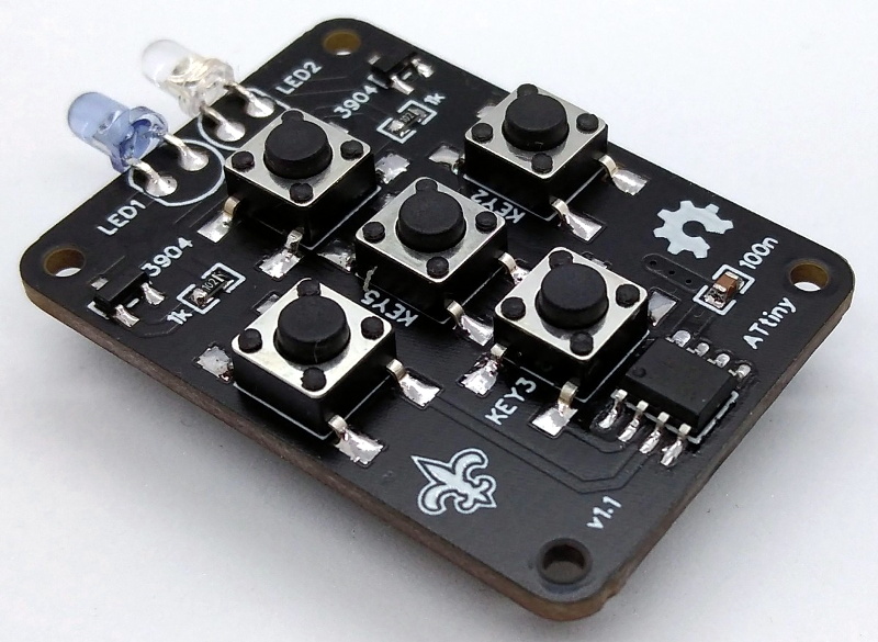
As you might have guessed from the name, this project is actually a larger version of the TinyRemote that [Stefan] put together previously. The documentation for that project goes a bit more into the nuts and bolts of talking IR, and is definitely worth a read if you’re into the low level stuff. For the original five button TinyRemote, the hardware consists of little more than a ATtiny13A microcontroller, a pair of IR LEDs, and the transistors to drive them.
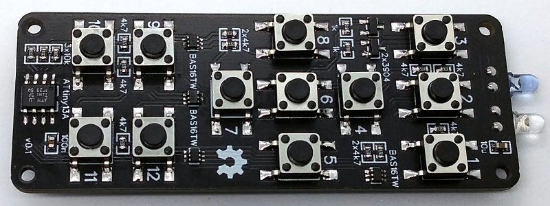
But on the XL, things are a bit trickier as there are now twelve buttons for the ATtiny13A to read. Obviously there aren’t enough pins to read so many buttons directly, but with a combination of BAS16TW diode arrays and resistors, [Stefan] is able to detect what button was pressed using the chip’s interrupt pin and ADC. Certainly a handy trick to have in the back of your mind, and the open source nature of this project gives you a great chance to see how it’s implemented.
Between this project and the impressive development board [Djordje Mandic] released recently, it seems we’re looking at something of an infrared hacking revival. Earlier this year we even saw the commercial release of an IR-equipped ESP8266 board.


I would prefer charlieplexed buttons (with diodes and internal pull-up resistors) instead of using ADC. But still, great project!
Now I’ve thought about it and found that the remote control could be woken from power-save mode by only three of the charlieplexed buttons (which is maybe the reason for using ADC).
I think the problem is with the self imposed limited I/O in that package. Charlieplexing requires extra parts which IMHO not as clean as multiplexing.
The thing to bear in mind is that you don’t need to read the key correctly on waking up. For ADC, you can measure the analog voltage afterwards. You just have to make sure that any key presses crosses the logic threshold (i.e. only uses a portion of the full range) to wake up.
For multiplexing keys, set all the rows to open drain pull down before sleep. Any key presses would trip the 3 I/O with pull up and wake up function. After that, you can poll for the actual key.
Attiny13a and Attiny85 were once the best bang/buck MCU’s you could find. Not anymore. Attiny13a’s went for $30/100pcs in 2018. Now: https://lcsc.com/product-detail/ATMEL-AVR_Microchip-Tech-ATTINY13A-SU_C9805.html .
The lowly digispark, something you could get for ~75c in 2018, goes for $5 today.
https://www.aliexpress.com/item/32828476349.html .
Remember that padauk pms150c 3c microcontroller? Now 26c on aliexpress https://www.aliexpress.com/item/1005002002147814.html. All gone on lcsc.
STM32? You’ve got to be joking.
IMO many of these hipster/hacker MCU’s will not get cheaper but instead gradually EOL’d as designers move away because of the persistent high prices and horrid supply chains even post pandemic. “chip shortage”?… partially. “price gouging”?… absolutely.
Atmel was way better when it wasn’t owned by Microchip…
Shipping from China was long enough that I have around 30 STM8 ($0.20) and 30 STM32F030 ($0.30) back when there were sales. Atmel chips weren’t that great of a deal back then. STM chips can use the same $2 hardware debugger, so development is a bliss.
Those traces are awfully close to the mounting holes. We learned this hard way troubleshooting an intermittent short in my engineering group. Why is mechanical mounting such an afterthought always? It is a plague on the I only thought as far as the board crowd.
Nylon bolts are a thing.
They are also not a silver bullet for bad PCB layout. See https://www.youtube.com/watch?v=SY4mBkB3CDw for consequences.
There are proper mounting holes (with pads) in Eagle CAD parts library with correct clearances for screw heads. The layout is such that some of the traces around the screw holes could be routed on the back side for proper clearances.
The DIY crowd isn’t known to clean up their schematic, component labelling, nor DFx.
I did a similar thing, but instead of interrupting the microcontroller, a mosfet is switched on by the buttion via diodes, thus keeping standby current to zero.
You can see a schematic of this approach in https://easyeda.com/LieBtrau/tv-remote-elderly.
seen it. In-fact mine is not much different (just a mosfet instead of interrupt pin). interestingly, mine was for elderly too, but more like gun shaped and made out of pipe-https://drive.google.com/file/d/19GJiHxL_0HetmSQSIA8_HbkJJmYXjcKA/view?usp=sharing
Used arduino nano so standby current was way higher thus mosfet was needed.
What about the rp2040, the naked chipset is supposed to be very cheap, and it’s got good support and plenty of I/0, and easy to prototype.
The RP2040 wouldn’t be a bad choice, but it would be extreme overkill, would consume more energy (I think, I haven’t dug into its low-power operation a ton) and the platform isn’t as well understood by the community as AVRs (yet). You could just as easily recommend any other 32-bit ARM MCU, as there’d be no real reason to use the RP2040’s coolest party trick, its state machines, in this application.
There’s something elegant about using an 8-bit for a simple, non-computationally-intensive application. I personally would’ve just gone for a higher-pin-count AVR and ditched all the passives, but to each their own.