A wall clock made from wires and electronic components

Form Follows Function In This Circuit Sculpture Clock

Electronic components are strictly functional objects: their appearance is determined by the function they’re meant to fulfil. But that doesn’t mean there’s no beauty in them. In fact, a whole discipline called circuit sculpture exists that aims to make beautiful shapes out of nothing more than electronic components and wires. Today we can show you [Maarten Tromp]’s latest work in this field: a wall-mounted clock that he’s christened the Clock Sculpture.

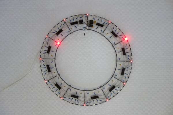
The clock’s main structure consists of two concentric rings made from galvanized steel wire, held together by twelve spokes. All components are soldered directly onto those two rings, with no additional mechanical support. Steel isn’t the greatest material for soldering to, but [Maarten] managed to make it work with a high-wattage soldering iron and a bit of plumbers’ flux.

The overall design is simple but clever: the outer ring holds 60 LEDs to indicate the minutes, with every fifth LED always illuminated dimly in order to provide a background reference in dark conditions. There are 24 LEDs on the inner ring to indicate the twelve hours as well as the “half-hours” in between. Without these, the dial would look a bit odd at 30 minutes past the hour.

Detail of a circuit sculpture clockA mains transformer, plus a single diode, a buffer capacitor and a 7805 regulator form a simple DC power supply, with its negative terminal connected to the steel frame. Time is kept by an ATtiny13A that counts mains frequency pulses. There’s no way to adjust the time: you’ll have to plug in the clock exactly at noon or midnight in order to synchronize it with the outside world. A crude method perhaps, but one that fits well with the clock’s bare-bones aesthetic.

The individual LEDs are driven by a set of twelve 74HC595 shift registers, all mounted dead-bug style between the two rings. Signals and power are carried between the chips by inconspicuous grey wires taken from old IDE cables; this gives the clock a clean, uncluttered appearance. [Maarten] has had the sculpture clock in his office for several months and while it apparently took some time to get used to, he claims it’s easy to read in bright and dark conditions.

Circuit sculpture has formed the basis for several stunning clock projects: this Tie Fighter-shaped clock for instance, or this insanely complex LED clock. Our 2020 Circuit Sculpture contest yielded many breathtaking designs, too.

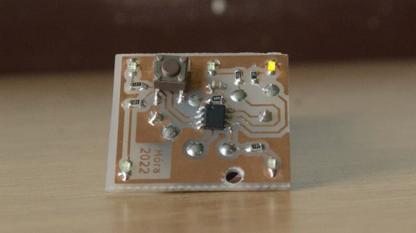
An ATTiny board that one of the students developed for this project, etched on single-sided FR4.

Electronics And C++ Education With An ATTiny13

When [Adam, HA8KDA] is not busy with his PhD studies, he mentors a group of students interested in engineering. To teach them a wide range of topics, he set out to build a small and entertaining embedded project as they watch and participate along the way. With this LED-adorned ATTiny13A project, [Adam] demonstrated schematic and PCB design, then taught C++ basics and intricacies – especially when it comes to building low-footprint software – and tied it all together into a real-world device students could take home after the project. His course went way beyond the “Hello world”s we typically expect, and some of us can only wish for a university experience like this.

He shares the PCB files and software with us, but also talks about the C++20 framework he’s developed for this ATTiny. The ATTiny13A is very cheap, and also very limited – you get 1K of ROM and 64 bytes of RAM. This framework lets you make good use of it, providing the basics like GPIO wiggling, but also things like low-power operation hooks, soft PWM with optional multi-phase operation support and EEPROM access. Students could write their own animations for this device, and he includes them in the repo, too!

In educational projects, it pays to keep code direct and clean, cruft-less and accessible to students. These are the things you can only achieve when you truly understand the tools you’re working with, which is the perfect position for teaching about them! [Adam] intends to show that C++ is more than suitable for low-resource devices, and tells us about the EEPROM class code he wrote – compiling into the same amount of instructions as an Assembly implementation and consuming the same amount of RAM, while providing compile-time checks and fail-safe syntax.

We’ve talked about using C++ on microcontrollers before, getting extra compile-time features without overhead, and this project illustrates the concept well. [Adam] asks us all, and especially our fellow C++ wizards, for our opinions on the framework he designed. Could you achieve even more with this simple hardware – make the code more robust, clean, have it do more within the limited resources?

What could you build with an ATTiny13, especially with such a framework? A flashy hairclip wearable, perhaps, or a code-learning RF-remote-controlled outlet. We’ve also seen a tiny camera trigger for endurance races,, a handheld Flappy Bird-like console, and many more!

An OSHW IR Remote Control Powered By The ATtiny13A

The new hotness in consumer electronics might be RF remotes based on protocols like Bluetooth Low Energy, but there’s still plenty of life left in the classic infrared remote. Especially with projects like TinyRemoteXL from [Stefan Wagner], which let you build and program an IR “clicker” of your own. Whether you want to spin up your own custom universal remote or create a beefed up version of the TV-B-Gone, this open source effort is a great place to start.

The original TinyRemote.

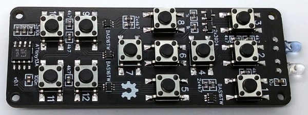
As you might have guessed from the name, this project is actually a larger version of the TinyRemote that [Stefan] put together previously. The documentation for that project goes a bit more into the nuts and bolts of talking IR, and is definitely worth a read if you’re into the low level stuff. For the original five button TinyRemote, the hardware consists of little more than a ATtiny13A microcontroller, a pair of IR LEDs, and the transistors to drive them.

But on the XL, things are a bit trickier as there are now twelve buttons for the ATtiny13A to read. Obviously there aren’t enough pins to read so many buttons directly, but with a combination of BAS16TW diode arrays and resistors, [Stefan] is able to detect what button was pressed using the chip’s interrupt pin and ADC. Certainly a handy trick to have in the back of your mind, and the open source nature of this project gives you a great chance to see how it’s implemented.

Between this project and the impressive development board [Djordje Mandic] released recently, it seems we’re looking at something of an infrared hacking revival. Earlier this year we even saw the commercial release of an IR-equipped ESP8266 board.

There Is No Spoon; Automatic Self Stirring Mug

Sometimes it’s helpful to realize the truth that there is no spoon. At least, not with [Ronaldo]’s automatic self-stirring mug. At first it was just a small propeller in the bottom of the mug that turned on by pushing a button in the handle, but this wasn’t as feature-rich as [Ronaldo] hoped it could be, so he decided to see just how deep the automatic beverage-mixing rabbit hole goes.

The first thing to do was to get a microcontroller installed to handle the operation of the motor. The ATtiny13a was perfect for the job since it’s only using one output pin to control the motor, and can be configured to only draw 0.5 microamps in power-saving mode. This ensures a long life for the two AAA batteries that power the microcontroller and the motor.

As far as operation goes, the motor operates in different modes depending on how many times the button in the handle is pushed. It can be on continuously or it can operate at pre-determined intervals for a certain amount of time, making sure to keep the beverage thoroughly mixed for as long as the power lasts. Be sure to check out the video below for a detailed explanation of all of the operating modes. We could certainly see some other possible uses for more interesting beverages as well.

Continue reading “There Is No Spoon; Automatic Self Stirring Mug”

Clocking (or Overclocking) An AVR

Some guys build hot rods in their garage. Some guys overclock their PCs to ridiculously high clock frequencies (ahem… we might occasionally be guilty of this). [Nerd Ralph] decided to push an ATTiny13a to over twice its rated frequency.

It didn’t seem very difficult. [Ralph] used a 44.2 MHz can oscillator and set the device to use an external clock. He tested with a bit-banged UART and it worked as long as he kept the supply voltage at 5V. He also talks about some other ways to hack out an external oscillator to get higher than stock frequencies.

We wouldn’t suggest depending on an overclock on an important or commercial project. There could be long term effects or subtle issues. Naturally, you can’t depend on every part working the same at an untested frequency, either. But we’d be really interested in hear how you would test this overclocked chip for adverse effects.

Now, if you are just doing this for sport, a little liquid nitrogen will push your Arduino to 65 MHz (see the video after the break). We’ve covered pushing a 20MHz AVR to 30MHz before, but that’s a little less ratio than [Ralph] achieved.

Continue reading “Clocking (or Overclocking) An AVR”

Tiny Audio Switcher Eliminates Repetitive Plug Swapping

usb-audio-switcher

[Phil] uses both his computer’s speakers and a set of headphones while working at his desk, but he was growing tired of constantly having to remove the headset from his sound card in order to insert the speaker plug. He’s been meaning to rig something up to make it easier to switch outputs, but never seemed to get around to it until he recently saw this LAN-enabled audio switcher we featured.

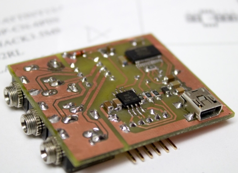
His USB-controlled switch features a single audio input and two audio outputs, which he mounted on a nicely done homemade double-sided PCB. The switch can be toggled using any terminal program, sending commands to the on-board ATtiny13A via an FT232R USB to serial UART chip.

The switch’s operation is really quite simple, merely requiring [Phil] to type in the desired audio channel into the terminal. The ATiny and a small relay do the rest, directing the audio to the proper output.

Hacked LED Christmas Lights

[Robert] wanted more out of his GE Color Effects G-35 LED Christmas lights. He reverse engineered and then hacked the protocol the lights use to communicate so that he can control each bulb. A 26-bit frame contains a 6-bit address, an 8-bit brightness value, and a 12-bit color value. The daisy chain topology of the data bus allows for modular bulbs with addresses enumerated during the startup of the string of lights. With this information, a 5 volt capable microcontroller is able to control a whole string of these lights with a refresh rate of up to 24Hz. In this case, [Robert] used an ATtiny13A microcontroller to control the string of lights. You can see a video of them in action after the break.

Also taken apart and analyzed, were the wireless transmitter and receiver that came with the lights, revealing a cheap ISM band receiver and transmitter module pair. Perhaps they will be useful for another project. We look forward to seeing people put these hacked lights to use throughout the year.

[via Make]

Continue reading “Hacked LED Christmas Lights”