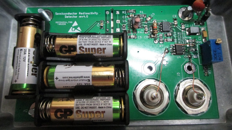
The instinctive reaction when measuring nuclear radiation is to think of a Geiger counter, as the low-pressure gas tube detectors have entered our popular culture through the Cold War. A G-M tube is not the only game in town though, and even the humble photodiode can be pressed into service. [Robert] gives us a good example, with a self-contained radiation detector head that uses a trio of BPW34s to do the job.
At its heart is a transimpedance amplifier, a not-often-seen op-amp configuration that serves as a very high gain current-to-voltage converter. This produces a spike for every radiation event detected by the diodes, which is fed to a comparator to produce a logic pulse. The diodes require a significant bias voltage, for which he’s used 48 V from a stack of 12 V photographic dry cells rather than a boost converter or other potentially noisy power supply. Such a sensitive high-gain device needs to be appropriately shielded, so the whole circuit is contained in a diecast box with a foil window to allow radiation to reach the diodes.
This isn’t the first BPW34-based radiation detector we’ve seen, so perhaps before looking for a Cold War era relic for our radiation experiments we should be looking in a semiconductor catalogue instead.


Could a bank of optoisolators be used for something similar? It would be a nice way to get dark packaging on something light sensitive.
A the BPW34 used here has around 7 square millimeters of collection area. Any (normal) optoisolator will have a much, much smaller sensitive region and consequently much lower sensitivity to radiation.
The phototransistor in an optoisolator is too small for this application, you need something substantially larger. BPW34 and similar have an active area of >7mm²! These photodiodes were common stuff some decades ago, used in IR remote control receivers before integrated modules were introduced. They are still available today from Vishay and Osram.
Would a common solar cell work for this application?
Generally, no. A large-area solar cell has too much capacitance, and solar cells also generally have very large dark current that would swamp the signal from an absorbed high-energy (x-ray or gamma) photon.
There are some smaller (150 sq. mm) high-quality monocrystalline solar cells like those from Ixys/Anysolar that can work in this application.
Large cells can be chipped.
Perhaps a neon bulb and similar gas discharge tubes can be used. Neon bulbs (often used as cheap ac voltage indicators) usualy need around 70V to start glowing, but if you fine tune the voltage right below that point, the discharge can be triggered by ionizing radiation. But there are other aspects which might affect the threshold voltage like temperature, magnetic field and perhaps even light, therefore i am not really sure this will work flawlessly. Otherwise the circuit would be very similar to one using geiger tube, except the voltage would be lower and neon bulb would be easier to obtain, making this build cheaper.
This has been done. It works sort of ok. Alpha is blocked by the glass, but beta and gamma will get through. IIRC, grinding an area of he envelope to nearly through gets a bit of alpha sensitivity.
See https://www.electronicdesign.com/technologies/test-measurement/article/21752395/simple-geiger-detector-uses-neon-glow-lamp for an example
a normal neon lamp used this way is literally a GM tube. A very crappy one, as it has no arc quenching, so a very long dead time.
Neon lamps often have radioactive electrodes or even radioactive gases added to mixture to lower striking voltage. this may interfere with radiation detection
Yeah, I’m trying to figure out if the batch of neon glow lamps I got on ebay from China have those additives or not. Seems glow lamps from US manufacturers in their heyday occasionally did and were clearly labelled.
But these lamps from China? No idea…
I got the impression it was gas additives, but Charles Wenzel seemed to think it was the electrodes themselves!? http://techlib.com/science/ion.html#Neon%20as%20Resistor
Check the links on these pages for more information on radiation detection without a G-M tube.
https://www.elektormagazine.com/labs/radiomush-radiology-of-mushrooms-30-years-after-tjernobyl
http://ziemann.web.cern.ch/ziemann/teaching/sj
As mentioned in the linked-to previous BPW34 work, Maxim describes this pretty thoroughly and details some important design considerations in their 2003 application note: https://www.maximintegrated.com/en/design/technical-documents/app-notes/2/2236.html
In the late seventies there was a solid state “geiger” counter in Popular Electronics. I can’t remember the sensor, I think it was one of those parts you had to get from the author.
in the wake of Three Mile Island, The Farm was making and selling solid stste counters, I neversaw technical details.
It was a diode reversed biased hmm cannot at moment remember which type
So, why *three*? The diodes are cheap, compared to the rest of the circuit.
More diodes = more collection area = more sensitivity.
And it’s sorely lacking in sensitivity: It only gets a count per minute or so (which is about right for background radiation with that amount of sensitive volume).
There’s plenty of acreage there for more diodes. Is more than three just too much capacitance for that poor OPA333?
Yes, the capacitance of the parallel diodes adds together and the pulses of current get averaged out too much to be detected.
Would a solution of more diodes in both parallel and series work to add sensitivity?
I don’t think series would work at all if you know what a diode is, all of them in series would have to trigger at the same time for a count to be registered.
I was referring to the instability of the op-amp from too much input capacitance — that’s demanding of the op-amp, and something the OPA333 used here is not particularly good about.
A lot of diode capacitance is not bad per se: Though you’re correct the voltage induced by an absorbed photon is reduced with higher capacitance, so is the noise to a great extent. So with the correct amplifier it can be a wash.
As mentioned by others there are issues with simply adding more photodiodes to the opamp input in an attemp to increase the collection area. However it seems like it would be possible to combine (sum or mix) the outputs of many groups of three photodiodes and one opamp. In small quantities the BPW34 photodiodes cost around a buck [1] while the OPA333 opamps cost around three bucks [2]. (A better and cheaper opamp might exist.) For the combiner one additional opamp would be required plus one additional resistor per channel being combined plus one additional feedback resistor for the combiner opamp. See [3] for a brief tutorial on audio combiners.
* References:
1. BPW34
https://www.mouser.com/Search/Refine?Keyword=BPW34
2. OPA333
https://www.mouser.com/Search/Refine?Keyword=OPA333
3. Op Amp Summing Amplifier: Virtual Earth Mixer
https://www.electronics-notes.com/articles/analogue_circuits/operational-amplifier-op-amp/virtual-earth-mixer-summing-amplifier.php
Nifty :-) The 48V only takes 4 of the little batteries. To do without batteries one can use a cascade of charge pumps/voltage doublers. Here is a sort of voltage-doubler quadrupler. They can run at low frequency with clean sine waves to avoid noise. In the circuit shown a 3.3V lithium will need 7 stages.
https://en.wikipedia.org/wiki/Voltage_multiplier#/media/File:Stacked_Villard_cascade.svg
IIRC you can characterize the photodiodes to see if they have a sweet spot for the bias voltage.
I make detectors out of old webcams. CCD and CMOS chips are excellent!
I would like to subscribe to your newsletter.
interesting, did you publish that somewhere?
Naw, neither my profession nor my ego needed the benefit of serious publication of the method. My purpose was simply that I wanted to make a cloud chamber to watch Alpha radiation tracks for my own pleasure, but its impossible to get dry ice around here. So when brainstorming on easy ways of seeing live decay products – I thought “hey, if something with the mass of an alpha particle slams right into a CCD or CMOS circuit, it simply is going to have to cause *something* to happen. And sure enough – if you just strip off the lenses and everything in front of the sensing chip. And then put a strong alpha emitter like some radium from an old clock, an Am-241 button from an smoke detector, or even a chunk of strong U238 containing ceramic pottery like Orange Fiestaware, and then completely isolate it from light. Hook it up to a graphics video input program – and you’ll be effectively getting a poor mans scintillation circuit.
It works remarkably well. I want to find a live input program that will let me change the output graphics more, maybe give me trails rather than sparks. Or get a coder to do it for me. But I can happily watch it for quite awhile.
That OP333 is a slick amplifier and I would like to hear more about the design requirements. OP333 is a chopper stabilized amp. The gain of 1000 in the stage labeled “Amplifier” reduces the practical bandwidth to around 1kHz. How fast are the detector pulses? Diodes set up like that are really fast. I wonder if some event amplitudes are being knocked down below the comparator level?
BTW, what voltage are the opamp supply rails?
The length of the pulses is pretty much determined by the time constant of the feedback network in the first stage, in that case we have a capacitance of 2.2 pF and a resistor of 10 GOhm (in the schematics) or 1 GOhm (in the hackaday project description), which will result in a time constant of 22 ms or 2.2 ms (not sure which feedback resistor is actually used). That shouldn’t be a problem at all even for a relatively slow amplifier such as the OP333.
So, where is the third diode?
@CRJEEA said: “So, where is the third diode?”
Huh? D1, D2, D3, on the schematic:
https://cdn.hackaday.io/files/1810327745273088/Circuit.pdf
The backsides of the three diodes are visible through the slot in the PCB, top middle of that lead photo.
The two obvious big things you might be mistaking for diodes are the back side of the BNCs
It might make sense to add a scintillator (like Polyethylene naphthalate film or rod) in front of the diodes to effectively increase the detection area by taking advantage of their light detection capabilities.
Gadolinium oxysulfide (like Lanex Fast) works much better than a plastic scintillator here, but still isn’t so great. Between the scintillator efficiency and the light coupling efficiency, you lose much of the signal.
At mid-range energies (say 30-80 keV), you get about a factor of two increase in sensitivity. Lower energies, you’re better off with the bare diode. At higher energies, the silicon becomes so transparent and insensitive that the scintillator does better.
First Sensor and Hamamatsu both make quite good large-area diode sensors with scintillators directly bonded to them, and the optical coupling efficiency is very good.
wouldn’t a hybrid power supply work here? A switcher to get 49-50V and then use a linear regulator to chop off a volt or 2, guaranteeing none of the noise makes it through?
Linear regulators aren’t fast enough to block the high frequency pulses.
A RC filter would probably work well for this, considering the current is close to zero.
The frequency of interest for the detector is low.
It isn’t that difficult to filter the high frequency noise from a power supply. A LC filter can easily take care of that and you can follow up with a linear regulator with high PSRR at high frequency.
* Analog Devices: Photodiode Circuit Design Wizard
Analog Devices Inc. (ADI – no affiliation) has an online “Photodiode Circuit Design Wizard” which IMO is really an interactive SPICE simulator.[1] The designs can be exported. Click the “Get Files” button and you will receive a .zip archive that has the results; a BOM in .csv format, a beautiful Design Report .pdf document with all the graphs, and (drum – roll) LTspice compatible simulations. You get LTspice .asc files for Transient, AC, and Noise simulations, plus Netlists. All three simulations work fine in LTspice, I tried them. This is great. Remember, ADI bought-out Linear Technologies Inc., the creators of LTspice and everyone assumed ADI would destroy LTspice (ADI does NOT have a customer-centered reputation in my experience). But that has not happened (so far). LTspice lives on and it’s still free and unencumbered – but not open-source (yes it’s Windows native but it will run under Wine in my experience).
By default, for the single stage simulation the wizard uses a generic PIN Photodiode macro model and an ADI AD8676 Ultra Precision, 36 V, 2.8 nV/sqrt(Hz) Dual RRO OpAmp [2]. The two stage sim uses the ADI ADA4625-2 36 V, 18 MHz, Low Noise, Fast Settling Single Supply, RRO, JFET OpAmp [3].
There’s a photodiode model selector button that has lots of photodiodes to choose from across severslmanufacturers, not just ADI. And yep, the BPW34/34S is there too! One hurdle I see with picking an actual photodiode is the Wizard asks you to enter the peak incident irradiance [4] in W/m^2, which is expected. This question is kind-of addressed in a reply on the ADI Engineer Zone forum [5] which refers to a table in the BPW34FASR datasheet [6]. How incidental irradiance in W/m^2 translates to a particle stike though is something entirely different. Anyway, it doesn’t really matter. What I want to see is the simulation results for the photodiode circuit’s transient response, bandwidth, and signal-to-noise, which is (within reason) possible without having to touch a soldering iron.
* References:
1. Analog Devices Inc. (ADI) – Photodiode Circuit Design Wizard
https://tools.analog.com/en/photodiode/
2. ADI AD8676 Ultra Precision, 36 V, 2.8 nV/sqrt(Hz) Dual RRO OpAmp
https://www.analog.com/en/products/ad8676.html
3. ADI ADA4625-2 36 V, 18 MHz, Low Noise, Fast Settling Single Supply, RRO, JFET OpAmp
https://www.analog.com/en/products/ada4625-2.html
4. Irradiance
https://en.wikipedia.org/wiki/Irradiance
5. How I can fix the value of this Peak Light Intensity (in W/m2)?
https://ez.analog.com/amplifiers/f/q-a/167730/photodiode-value-of-peak-light-intensity
6. VBPW34FAS, VBPW34FASR
https://www.vishay.com/product?docid=81127
A photoresistor is a semiconductor device with a relatively large active area. I’d imagine a particle hitting it in complete darkness would cause a detectable event. Maybe it is 10 megaohms in total darkness. You should be able to wire up some very high current gain system around that. Even 2 transistors correctly arranged could give a current gain of around 300*300 = 90000.
The original Nukalert used a photoresistor (cadmum sulfide) with a clever optical bias arrangement. But a photoresistor by itself is a poor radiation detector: The actual radiation detection element was gadolinium oxysulfide phosphor that is optically coupled to it (along with the clever optical bias). The GdOS converted incoming x-ray & gamma photons to green light photons. The advantage of this scheme was its very long battery life, and very cheap to produce. (This is important when you want to flog as many as possible to a whipped-up, fearful populace.)
Would a Silicon Photomultiplier (SiPM) work for this application?
No. A SiPM (avalanche mode photodetector) will have even worse sensitivity than a BPW34, because it has a smaller sensitive volume. It also has (relatively speaking) enormous dark current: many thousands of pulses per second just due to thermal background. That would totally swamp the approximately one pulse per minute you’d get from normal background radiation. Even cooling to liquid nitrogen temperatures would not be enough to distinguish normal background radiation from the thermal noise.
BTW: a BPW34 can be operated in avalanche (“Geiger”) mode too. You don’t need to pay the kilobuck for a purpose-designed SiPD’s pedigree. Same deal though: tons of dark current noise.
The voltage required isn’t actually that much higher than used in the circuit here, either. It’s variable depending on supplier (and lot, too, likely), but around 60 V.
Thanks!
SiPM parts are now in the decibuck range:
https://www.digikey.com/short/m93mm9rc
I’m just looking for a cool project as an excuse to buy a few :)