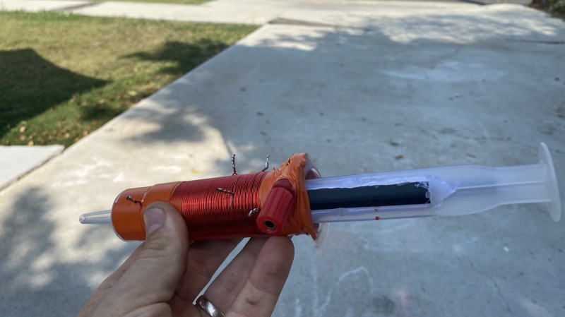
Amateur Radio as a hobby has a long history of encouraging experimentation using whatever one might have on hand. When [Tom Essenpreis] wanted to use his 14 MHz antenna outside of its designed frequency range, he knew he’d need an impedance matching circuit. The most common type is an L-Match circuit which uses a variable capacitor and a variable inductor to adjust the usable frequency range (resonance) of an antenna. While inefficient in some specific configurations, they excel at bridging the gap between the 50 ohm impedance of the radio and the unknown impedance of an antenna.
No doubt raiding his junk box for parts, [Tom] hacked together a variable capacitor and inductor using ferrite rods from AM radios, hot glue, magnet wire, copper tape, and some surplus 60ml syringes. You can see that he ground out the center of the plunger to make room for ferrite rods. Winding the outside of the syringe with magnet wire, the alignment of the ferrite can be adjusted via the plunger, changing the characteristics of the element to tune the circuit. [Tom] reports that he was able to make an on-air contact using his newly made tuner, and we’re sure he enjoyed putting his improvised equipment to use.
If Amateur Radio isn’t your thing, then maybe we can entice you with this syringe based rocket, syringe actuated 3D printed drill press, or vacuum syringe powered dragster. Have your own hack to share? By all means, submit it to the Tip Line!


Imagine an electromechanical pneumatic automatic antenna tuner…
I am not a HAM and have really little knowledge about HF, but i know that in some bands the TX-power can he huge and so the voltages at the antenna. So having a non-conductive plastic tube filled with air between your antenna tuner and your control device might be a good thing?
It will have poor efficiency due to the AM ferrite being extremely lossy at 14 MHz.
He does mention something about inefficiency and it not being a problem. In one of Doug Demaw’s books as I recall he claims the ferrite eventually acts like air at higher frequencies.
I used such a ferrite rod in 80m fox transmitter (3.5MHz) and the losses were in the ballpark of 5 dB compared to a ferrite mix proper to the frequency.
What is this mysterious American Magnet Wire that I see all over the internet nowadays and what has it got to do with magnets? Is it made from steel?
Magnet wire is copper wire with an thin insulative enamel coating. I guess it’s named as such because it’s commonly used to create electromagnetic coils, namely for motor windings/speaker voice coils/solenoids/wire wound inductors/etc.
Or, if you don’t have a syringe, some corflute/coroplast material can work as the coil former with the ferrite being slid inside it. Details here: https://www.youtube.com/watch?v=NyKu0qKVA1I