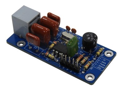
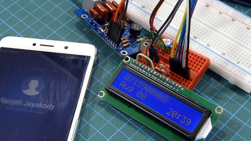
It’s no secret that the era of the landline telephone is slowly coming to a close. As of 2020, it was estimated that less than half the homes in America still subscribed to plain old telephone service (POTS). But of course, that still amounts to millions upon millions of subscribers that might get a kick out of this Arduino caller ID developed by [Dilshan Jayakody].

Truth be told, until this point, we hadn’t really given a lot of thought to how the caller ID system works. But as [Dilshan] explains, you can actually pick up a dedicated IC that can decode incoming caller data that’s sent over the telephone line. In this case he’s using a Holtek HT9032D, which comes in a through-hole DIP-8 package and can be picked up for around $2 USD. The chip needs a handful of passives and a 3.58 MHz crystal to help it along on its quest, but beyond that, it’s really just a matter of reading the decoded data from its output pin.
To display the caller’s information, [Dilshan] is using an Arduino Uno and common 16×2 HD44780 LCD. As a nice touch, the code will even blink the Arduino’s onboard LED when you’ve missed a call. As a proof of concept there’s been no attempt to condense the hardware or ditch the breadboard, but it’s not hard to imagine that all the components could be packed into a nice 3D printed enclosure should you want something a bit more permanent.
We’ve seen caller ID data being collected in previous projects, but they used a USB modem combined with a software approach. We really like the idea of doing it with a cheap dedicated IC, though we’ll admit this demonstration would probably have been a bit more exciting a decade ago.


AI to detect spammers?
He’s such a designated engineer but he should cut the leads first, then solder unless he likes dealing with cracked solder joints.
Ehmmm, he’s not doing it very different from what used to be industry standard (regarding, low quantity, hand assembled through-hole PCB production. First solder and then cut.
Cutting the leads first and then soldering them is making things much more difficult in many ways.
But for those who worry about stress introduced into the solderjoint due to the cutting process, you can always reflow the joint a second time, keeping the proper flux levels in mind.
Interesting. I did something similar long time ago with an m8870 dedicated dtmf and an 8051 or 8031 chip. All in assembler. The good old days🤣
Wow! brings back memory of a project I did during my engineering college days in 1999! CM8870 DTMF decoder, 8 bit PIC micro (16F877A !) and a HD44780 LCD. I also implemented a small lookup in micro to display caller name :) . Arduino was not around back then!
Good story. You never know when something like this may hold that nugget of info a DIY’er needs for some other project. Thx for the writeup.
I wonder how many actually use their landline. Everyone in my area ‘has a landline’, because DSL is the only option, but I don’t know anyone who actually has a phone plugged in. Similarly when I used to live in the city it was often cheaper to do a tv+internet+phone bundle than just tv+internet (I think there are telecom perks per number given out).
So even though “less than half the homes in America still subscribed to plain old telephone service (POTS)” I’d hazard a guess that most of them go unused. Even the luddites and older people I know have ported their numbers over to cell phones.
Neat project though. As a kid, learning how the POTS worked was one of the things that set me down the engineering path.
As you alluded to. We still have local phone, not POTS, but Spectrum cable internet/phone. We like having a central common phone. It’s the number we give out to those who need to contact us. We don’t feel we need to be ‘connected’ 24×7 via cell phones although I have carry one for work (company pays for the service). People can leave a message and when we get home, we check and call back if necessary. Can’t wait to retire and not have carry the cell all the time….
Cleaning out my basement I found an old caller ID unit I use to use. It took me a good 5 minutes to recognize what it was and remember what it was used for!
Great work! Would this work with the caller ID format from an old Panasonic pbx?
Lol not meant as a reply…
reminds me i need to finish my telephone project…
thanks for the info,
just a note to those who dont know;
he is only using a dedicated chip because he wants to do it that way,
the communication is nothing special or secret,
its just outdated dialup while onhook, slipped between the 90vac rings…
bell 101? 102? 201? 202? i cant remember,
but its a very simple modulation with no negotiations or carrier,
STMF(STDF?), in contrast to the much more complicated DTMF we use for dialing.