No one likes a flickering light source, but lighting is often dependent on the quality of a building’s main AC power. Light intensity has a close relation to the supply voltage, but bulb type plays a role as well. Incandescent and fluorescent bulbs do not instantly cease emitting the instant power is removed, allowing their output to “coast” somewhat to mask power supply inconsistencies, but LED bulbs can be a different story. LED light output has very little inertia to it, and the quality of both the main AC supply and the bulb’s AC rectifier and filtering will play a big role in the stability of an LED bulb’s output.
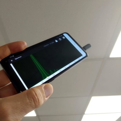
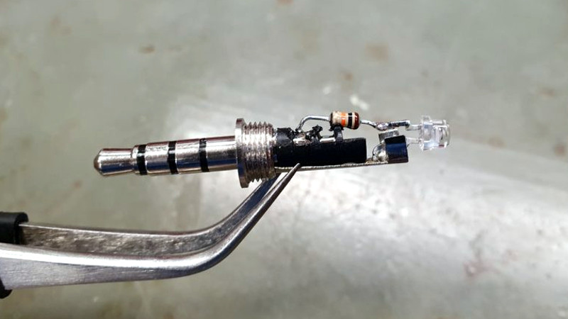
[Tweepy] wanted to measure and quantify this effect, and found a way to do so with an NPN phototransistor, a resistor, and a 3.5 mm audio plug. The phototransistor and resistor take the place of a microphone plugged into the audio jack of an Android mobile phone, which is running an audio oscilloscope and spectrum analyzer app. The app is meant to work with an audio signal, but it works just as well with [Tweepy]’s DIY photosensor.
Results are simple to interpret; the smoother and fewer the peaks, the better. [Tweepy] did some testing with different lighting solutions and found that the best performer was, perhaps unsurprisingly, a lighting panel intended for photography. The worst performer was an ultra-cheap LED bulb. Not bad for a simple DIY sensor and an existing mobile phone app intended for audio.
Want a closer look at what goes into different LED bulbs and how they tick? We have you covered. Not all LED bulbs are the same, either. Some are stripped to the bone and others are stuffed with unexpected goodness.


It’s brilliant in its simplicity!
Yeah, that’s the second simplest way to detect LED flicker I know, the first being just shaking your hand really fast and seeing if it “strobes”. This is more accurate though.
and fully compatible with iPhone, nice.
Nope not anymore. Apple hasn’t put an audio jack on an iPhone since the… IPhone 7?
Apple users should check out Buy-a-day
So you need a $9 adapter. https://www.apple.com/shop/product/MMX62AM/A/lightning-to-35-mm-headphone-jack-adapter
You know what else doesn’t come with a headphone jack anymore? Almost every flagship Android phone.
The 3.5mm TRRS audio jack is a niche connector now. The vast majority of users don’t need it, Bluetooth audio is good enough for nearly every use, so the space that would have been taken up by it is better used for something else.
I’m guessing that one reason (other than they can make for money selling their expensive Bluetooth earplugs) is that getting rid of the 3.5 mm socket eliminates one of the two water ingress points into a phone. The other being the USB charge socket. But I “guess” those can be either more easily isolated or come in water-proof versions. Or you can strictly rely on magnetic coupled charging to make a phone waterproof.
One possible downside was demonstrated by my latest phone when its battery gassed out a bit, making the case bulge and pop open in the middle, exposing the sticky sealer edge all around the perimeter and making it impossible to open and fix! Buyer beware!
Yes, I have to admit is overpass my PWM detector using a photodiode and my DS212…
Inductive ballast fluorescents actually flash red, then blue 120 times a second. If you have a video camera with reduced exposure time mode, try setting it to 1/1000th of a second(or less) and setting the frame rate to 30 or 60 fps (in 60 Hz power countries). The frequency won’t quite match the line frequency so you can see the fluorescent source slowly change from a blue flash (corresponding to the mercury discharge) and a subsequent reddish flash from the other phosphors in the resulting video (turn off ‘auto white balance’ and ‘auto exposure’). The eye averages the flash pairs to provide the perception of something like ‘white’. It’s surprising to see how much of the cycle is simply dark. Electronic ballasts flash frequently enough to reduce the phosphor brightness ripple to just a few percent, but the gas discharge is still an abrupt pulse and relatively low duty cycle, even at 20kHz.
Thought i was creative by connecting an led to my scope input. This is next level simplicity.
I’m guessing you meant that you connected your scope DIRECTLY to the LED being tested, right?
But any “plain old” LED can also act as a photocell in that they generate a voltage (albeit small) when a light is shined on them, so using one to test LED light flicker is simpler and doesn’t require a resistor. On a microprocessor, just connect the LED “sensor” to an analog input. I’m guessing that (as I have tested it) any color LED will work — even an IR LED even though lighting LEDs are actually blue with phosphors to create shades of white. I only ever tested this with red LEDs but that was 40 some years ago while in college. If you need faster response time, then put a high-value resistor in parallel with the LED to drain off the voltage to speed turn-off time due to charge storage (i.e. capacitance) effects.
Nice..i wanted to build something around an arduino and an counter and thresholding, but this is muuuch easier.
So, i only have LEDs at hand and with a quick check with my multimeter i see voltages to up to 1.5V .. that does not seem safe to put into a mobile phone mic jack?
Is it because the multimeter has some resistor built in? I’m probably missing something obvious?
Resistor ladder to drop the voltage.
Albeit the values demand experimentation
I’d used leds to detect the light. Like you said, they put out a tiny voltage when light shines on them. Worked fine on my scope, just led connected directly as a light sensor.
Tried a few different colours, they all worked well. I should try a cob array, see if that puts put more voltage.
With just an incandescent or well-filtered LED lamp, this would also work as a simple frequency counter.
Oops, I mean “tachometer”. I shouldn’t post while distracted.
It would be interesting to aim it a an old CRT TV. For half a century we buzzed our eyes with the boob tube. Now that we have LCD’s it should be quieter. Those whirling disc DLP’s gave off a buzz also, but now it’s digital editing with all the pop and flash.
As proud owner of early whirling disc DLP, can confirm rainbow fringes when you move your eyes. Bummer.
That fringing effect only happened on projector bulb color wheels and no the later LED “color wheels’, although both types had to be well aligned.
I wonder how well it can detect data leaks.
I tend to be able to see lights flickering that most people say are solid. The first smartphone keyboard I ever saw, the keyboard flickered to me, and everyone else thought I was joking; I’m guessing that their update frequency was right on the ‘edge’. I love the power savings with home LEDs, but many of them I’ve tried drive me nuts. Honestly considered developing a constant current driver I could make and swap out in the lighting in my house.
Anyone else have this issue?
Yep, though less bad. (Have added extra smoothing capacitors to some led bulbs that where exceptionally bad, they still flicker but less anoyingly)
Yes, I have this!
I can reliably see flickering up to around 70-ish Hz.
Instantly tell if you had a CRT refresh rate set to 60Hz, (I would always have to change it to 75Hz to not see the flickering).
I still notice the flickering on newer high refresh rate (gamer) LCDs, when they are at 60Hz. Older LCDs not so much.
And definitely can tell the difference in LED drivers in (full wave vs. half wave rectifier).
Certain OLED panels on phones flicker really bad.
Car tail lights are the worst!!!
Please up the PWM frequency!!
When LED clocks were ubiquitous, I could often see them jitter, especially with head motion, that created a strobing effect. My first LED clock was a home-made back in the 70s while going to college. It used an MK5017 PMOS Mostek clock chip (see http://www.decodesystems.com/mk5017.html) driving 4 ancient, 7/8 inch tall, red Dialight 7-segment LEDs, with 2 red LEDs for the colon and another for the AM/PM indicator. It had to be transformer powered since its timing is derived from the power-line frequency and was also used to multiplex the LEDs (common anode I think?). All parts from 70s surplus stores, especially Poly Pak but also James Electronics (now, Jameco), John Meshna, Burstein-Applebee, McGee Radio, etc. It was the fact that the multiplex timing was derived from the power-line that caused the flicker. I even designed and etched my own single layer PCB the “old tech” way with taped layout, one-to-one transfer to a film, and then direct contact exposure to a photo-sensitive copper-clad phenolic PCB. I’m sure it cost way more than buying one, but it was a stepping-stone to my 40+ year EE career and a lot of fun.
Even some newer multiplexed LEDs still cause flicker to me.
A phototransistor should be easily home made decapping a regular (silicon) transistor in metallic case. I did that as a kid and it worked just fine. As a side note, connecting the biasing resistor and transistor collector to an audio amplifier, as below, provided some interesting sounds like from burning matches, remote controls, CRT tv, etc.
+V (9V)
|
|
\
/ (Biasing resistor, 10k ohm)
\
/
|
| 220nF cap
|____| |_______ To amp
| | |
|
\ Collector
\ |
\|___ Base (n.c.) NPN transistor
/|
/ | Emitter (to GND)
|
|
|
GND
With a file remove patiently the top side of the metallic transistor until the transistor die is visible.
I developed a smartphone app that measures light flickering with the use of the camera of the smartphone. It measures the difference in percent from the highest light output to the lowest.
Android, https://play.google.com/store/apps/details?id=com.contechity.flicker_meter
iOS, https://apps.apple.com/us/app/led-light-flicker-meter/id1672848632?platform=iphone
Please let me know if it is useful and if there are any improvements needed! apps@contechity.com