We may be a bit biased, but the storage media of yesteryear has so much more personality than that of today. Yes, it’s a blessing to have terabyte SD cards smaller than your pinky nail and be able to access its data with mind-boggling speed. But there’s a certain charm to a mass storage device that can potentially slice off your finger.
We’re overstating the dangers of the venerable paper tape reader, of course, a mass storage device that [David Hansel] recreated a few years back but we only just became aware of. That seems a bit strange since we’ve featured his Arduino-based Altair 8800 simulator, which is what this tape reader is connected to. Mechanically, the reader is pretty simple — just a wooden frame to hold the LEGO Technic wheels used as tape reels, and some rollers to guide the tape through a read head. That bit is custom-made and uses a pair of PCBs, one for LEDs and one for phototransistors. There are nine of each — eight data bits plus the index hole — and the boards are sandwiched together to guide the paper tape.
The main board has an ATmega328 which reads the parallel input from the read head and controls the tape motor. That part is important thanks to Altair Basic’s requirement for a 100- to 200-ms delay at the end of each typed line. The tape reader, which is just being used as sort of a keyboard wedge, can “type” a lot faster than that, so the motor speed is varied using PWM control as line length changes.
When the job at hand is measuring something with micron-range precision, thoughts generally turn to a tool with a Mitutoyo or Starrett nameplate. But with a clever design and a little electronics know-how, it turns out you can 3D print a displacement sensor for measuring in the micron range for only about $10.
While the tool that [BubsBuilds] came up with isn’t as compact as a dial indicator and probably won’t win any industrial design awards, that doesn’t detract from its usefulness. And unlike a dial indicator — at least the analog type — this sensor outputs an easily digitized signal. That comes courtesy of a simple opto-interrupter sensor, which measures the position of a fine blade within its field of view. The blade is attached to a flexure that constrains its movement to a single plane; the other end of the flexure has a steel ball acting as a stylus. In use, any displacement of the stylus results in more or less light being received by the phototransistor in the opto-interrupter; the greater the deflection, the less light and the lower the current through the transistor. In addition to the sensor itself, [Bub] printed a calibration jig that allows precision gauge blocks or simple feeler gauges to be inserted in front of the stylus. The voltage across the emitter resistor for these known displacements is then used to create a calibration curve.
Electric guitar pickups rely on steel strings interfering with a magnetic field, the changes in which are picked up with coils of wire. That doesn’t work with nylon strings, because they don’t tend to perturb magnetic fields nearly as much, beyond some infinitesimal level that some quantum physicist could explain. So what do you do? You follow [Simon]’s example, and build an optical pickup instead.
The concept is simple. You place an LED and a phototransistor in a U-shaped channel, and place it so that the string runs through it. You repeat this for each string. Thus, as a string vibrates, it interrupts the light travelling from the LED to the phototransistor. This generates a voltage that varies with the frequency of the string’s vibration. Funnily enough, this type of pickup will work just fine on both nylon and steel strings, if you were so inclined to try it.
[Simon] designed a nifty PCB with six LED-phototransistor pairs (using off-the-shelf interruptor sensors) for use with a nylon-stringed guitar. He reports that sound from the strings comes through clearly, but that there is some noise that is evident in the pickup’s output, too. Listening to the demo, it seems to capture the sound of the nylon strings well, it’s just a shame that the noise floor is so high.
If you prefer your guitar pickups to be the regular magnetic kind, you can always wind your own from scrap. Demo after the break.
Proximity sensors are common enough in automation projects that we hardly give them a second thought — pick something with specs that match the job and move on. But they can be fussy to get adjusted just right, a job made more difficult if they’re located in some out-of-the-way corner.
But where lies a challenge, there’s also an opportunity, as [Ido Gendel] shows us with this remote-controlled proximity sensor. The story behind this clever little hack starts with an off-the-shelf sensor, the kind with an IR LED and a phototransistor pointed in the same direction that gives a digital output when the light bouncing back into the phototransistor exceeds a certain threshold. It was setting the threshold that gave [Ido]’s client trouble, so [Ido] decided to build a programmable drop-in replacement to make the job easier.
The first try at this used an OBP732 reflective transmitter and an ATtiny202 microcontroller and had three pads on the PCB for programming. This still required physical contact for programming, though, so [Ido] had the idea to use the sensor for wireless IR programming. The microcontroller on version two was switched to an ATtiny212, and a couple of components were added to control the power of the LED so the sensor could do double duty. A programmer using the same sensor and a USB-to-UART adapter completes the system, and allows the sensor threshold to be set just by shining the programmer in its general direction from up to 25 cm away.
We think that getting multiple uses from a single sensor is pretty clever, so hats off for this one. It’s not the first time we’ve featured one of [Ido]’s projects, but it’s been quite a while — this one-clock-cycle-a-day Shabbat clock was the most recent, but you can clearly see the roots of the sensor project in this mouse pointer data encoder that goes all the way back to 2015.
Computer memory has taken on many forms over the years, from mercury-based delay-line tubes to handwoven magnetic core. These days, volatile storage using semiconductors has become ubiquitous with computing, but what if there was a better way? [Michael Kohn] has been working on a new standard for computer memory that uses glow in the dark stickers.
Clearly we jest, however we’re still mighty impressed by the demonstration. Eight delightful star-shaped phosphorescent stickers represent eight bits of memory, totaling one byte. The glow in the dark material is stuck to the inside of short cylinders, each of which contains a white LED and a phototransistor. The memory array is wired up to an iceFUN FPGA board, which is then connected via level shifters to a Western Design Center MENSCH single board computer.
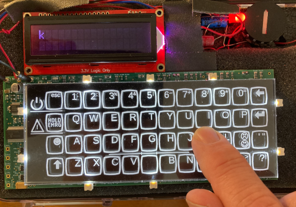
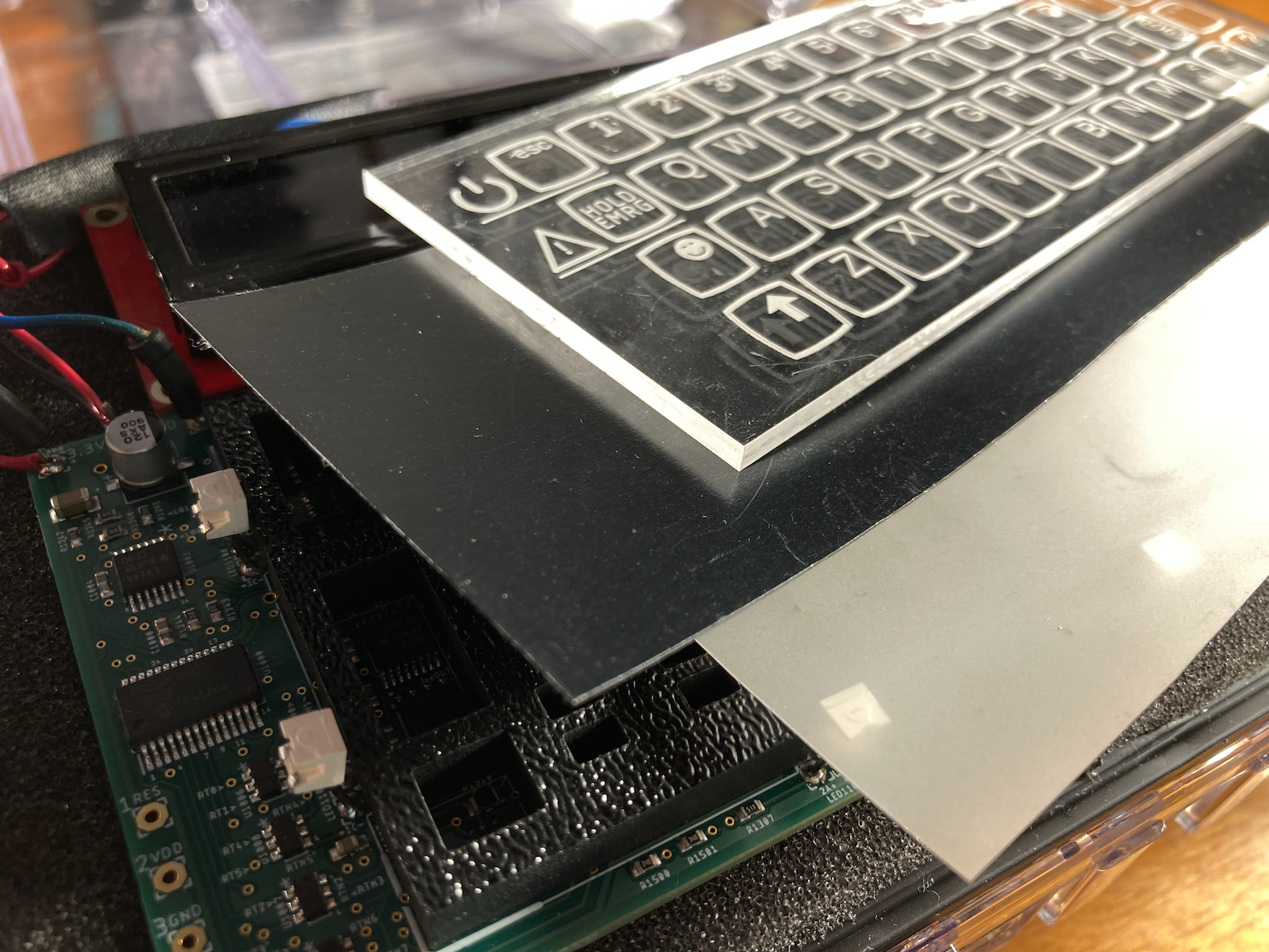
Making keyboards is easy, right? Just wire up a bunch of switches matrix-style to a microcontroller, slap some QMK and a set of keycaps on there and you’re good to go. Well, yeah, that might work for cushier environments like home offices and Hackaday dungeons, but what if you need to give input under water, in a volatile area, or anywhere else you’d have to forego the clacking for something hermetically sealed? Mechanical switches can only take you so far — at some point, you have to go optical.
This gorgeous keyboard works with reflected IR beams to determine when a finger is occupying a given key site (because what else are you going to call them?). Each key site has an IR LED and a phototransistor and it works via break-beam.
[BenKoning] wanted a solution that would be easy for others to build, with a low-cost BOM and minimal software processing cost. It just so happens to be extremely good-looking, as well.
The reason you can’t see the guts is that black layer — it passes infrared light, but is black to the eye. The frosted layer diffuses the beams until a finger is close enough to register. Check it out in action after the break, and then feed your optical key switch cravings with our own [Bob Baddeley]’s in-depth exploration of them.
Regular readers will know that Hackaday generally steers clear of active crowdfunding campaigns. But occasionally we do run across a project that’s unique enough that we feel compelled to dust off our stamp of approval. Especially if the campaign has already blasted past its funding goal, and we don’t have to feel bad about getting you fine folks excited over vaporware.
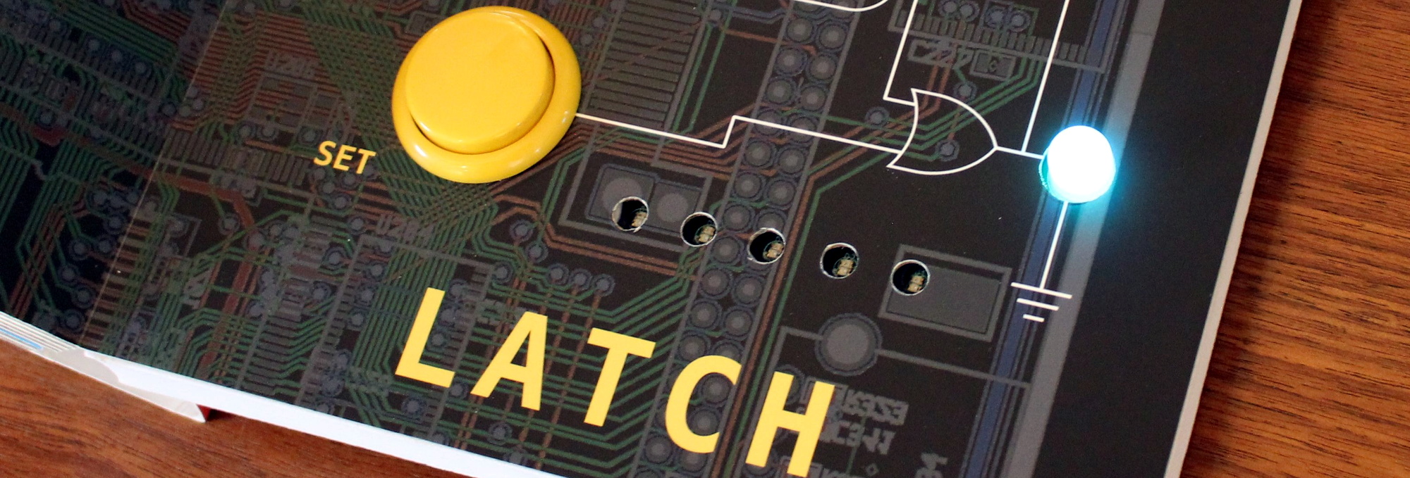
It’s with these caveats in mind that we present to you Computer Engineering for Babies, by [Chase Roberts]. The product of five years of research and development, this board book utilizes an internal microcontroller to help illustrate the functions of boolean logic operations like AND, OR, and XOR in an engaging way. Intended for toddlers but suitable for curious minds of all ages, the book has already surpassed 500% of its funding goal on Kickstarter at the time of this writing with no signs of slowing down.
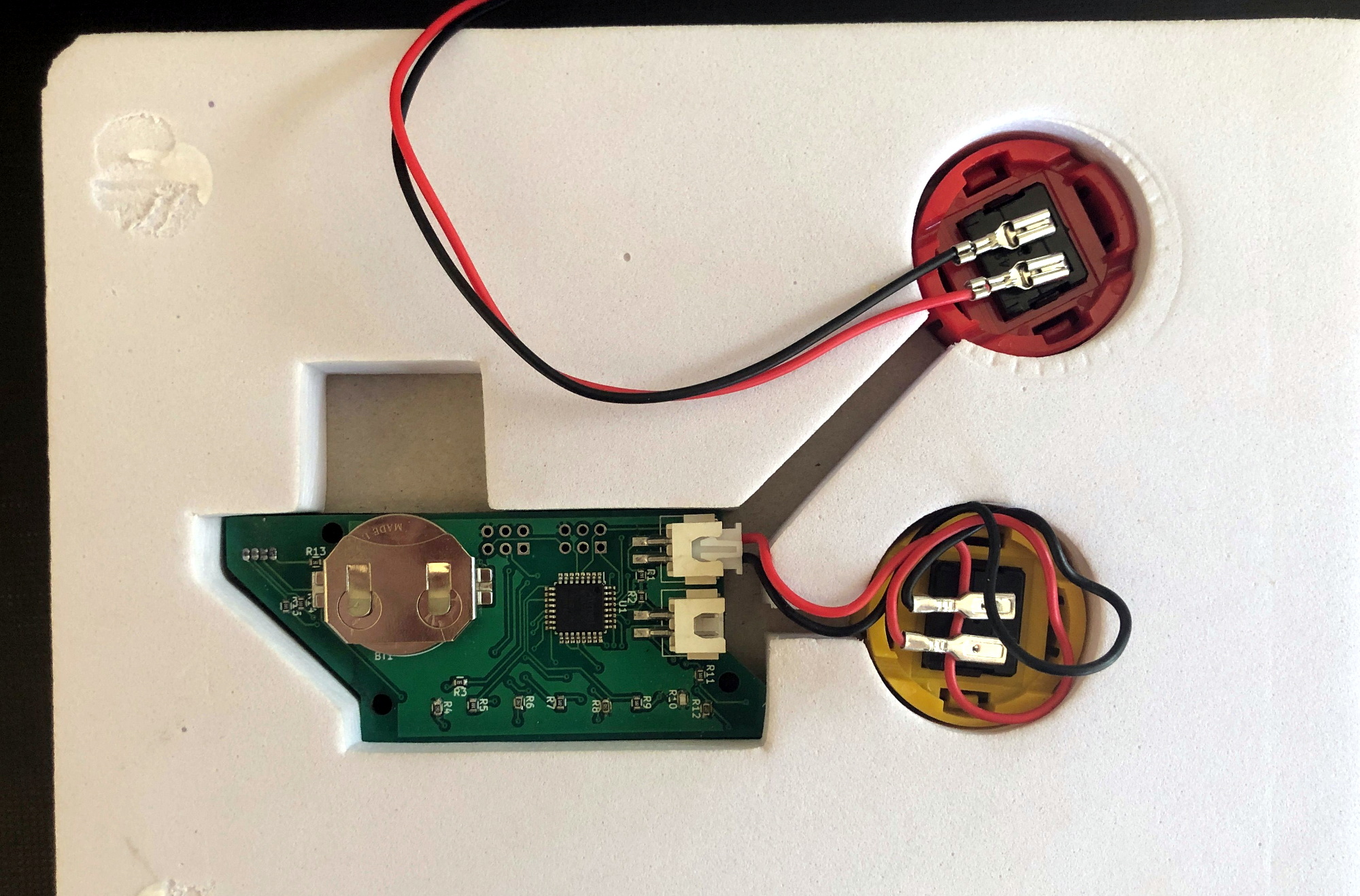
The electronics as seen from the rear of the book.
Technical details are light on the Kickstarter page to keep things simple, but [Chase] was happy to talk specifics when we reached out to him. He explained that the original plan was to use discreet components, with early prototypes simply routing the button through the gates specified on the given page. This worked, but wasn’t quite as robust a solution as he’d like. So eventually the decision was made to move the book over to the low-power ATmega328PB microcontroller and leverage the MiniCore project so the books could be programmed with the Arduino IDE.
Obviously battery life was a major concern with the project, as a book that would go dead after sitting on the shelf for a couple weeks simply wouldn’t do. To that end, [Chase] says his code makes extensive use of the Arduino LowPower library. Essentially the firmware wakes up the ATmega every 15 ms to see if a button has been pressed or the page turned, and updates the LED state accordingly. If no changes have been observed after roughly two minutes, the chip will go into a deep sleep and won’t wake up again until an interrupt has been fired by the yellow button being pressed. He says there are some edge cases where this setup might misbehave, but in general, the book should be able to run for about a year on a coin cell.
[Chase] tells us the biggest problem was finding a reliable way to determine which page the book was currently turned to. In fact, he expects to keep tinkering with this aspect of the design until the books actually ship. The current solution uses five phototransistors attached to the the MCU’s ADC pins, which receive progressively more light as fewer pages are laying on top of them. The first sensor is exposed when the second page of the book is opened, so for example, if three of the sensors are seeing elevated light levels the code would assume the user is on page four.
Opening to the last page exposes all five light sensors.
The books and PCBs are being manufactured separately, since as you might expect, finding a single company that had experience with both proved difficult. [Chase] plans on doing the final assembly and programming of each copy in-house with the help of family members; given how many have already been sold this early in the campaign, we hope he’s got a lot of cousins.
So what do you do with an Arduino-compatible book when Junior gets tired of it? That’s what we’re particularly interested in finding out. [Chase] says he’s open to releasing the firmware as an open source project after the dust settles from the Kickstarter campaign, which would give owners a base to build from should they want to roll their own custom firmware. Obviously the peripheral hardware of the book is fairly limited, but nothing is stopping you from hanging some sensors on the I2C bus or hijacking the unused GPIO pins.
If you end up teaching your copy of Computer Engineering for Babies some new tricks, we’ve love to hear about it.


 The concept is simple. You place an LED and a phototransistor in a U-shaped channel, and place it so that the string runs through it. You repeat this for each string. Thus, as a string vibrates, it interrupts the light travelling from the LED to the phototransistor. This generates a voltage that varies with the frequency of the string’s vibration. Funnily enough, this type of pickup will work just fine on both nylon and steel strings, if you were so inclined to try it.