There are many scanners — both commercial and homemade — that can take a variety of scans or images of a 3D object and convert it into something like a 3D printable file. When the process works, it works well, but the results can be finicky at best and will require a lot of manual tuning. According to [Samuel Garbett], you might as well just draw your own model using Blender. He shows you how using a Red Bull can which, granted, isn’t exactly the most complicated thing ever, but it isn’t the simplest either.
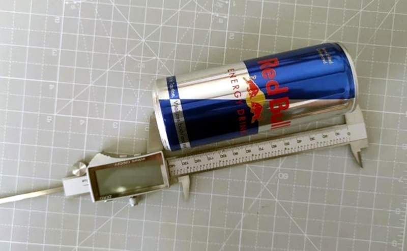
He does take one photo of the can, so there is a camera involved at some point. He also takes measurements using calipers, something you probably already have laying around.
Since it is just a can, there aren’t many required pictures or measurements as, say, a starship model. Once you have the measurements, of course, you could use the tool of your choice and since we aren’t very adept with Blender, we might have used something we think is easier like FreeCAD or OpenSCAD. However, Blender has a lot of power, so we suspect making the jump from can to the USS Enterprise might be more realistic for a Blender user.
Besides, it is good to see how other tools work and we were surprised that Blender could be relatively simple to use. Every time we see [Jared’s] channel, we think we should learn more about Blender. But if you have your heart set on a real scanner, there are plenty of open source designs you can print.


Even though I was building/operating 3D-Scanners for a living, I often told people, that certain objects are far easier modelled than scanned. If it happens to be an engineered part with sane dimensions it is also more accurate. You just need to have a process for measuring your way around the object and voila.
Totally true! As an Mech. Engineer I need to “copy” or modify parts quite often.
Stuff gets nasty when the Engineer of the original used chamfers and fillets everywhere or made heavy use of freeform geometry. But especially with parts created in the metric system, it’s often quite obvious what dimensions were meant to be evennif slightly off…
Once you figure out if the original engineer used Metric or was high, then it’s pretty easy to round off to the nearest sensible measurement and build it off that. Chamfers and fillets aren’t usually too bad since they are frequently aesthetic or just to break a sharp edge, they’re also usually whole numbers (1/16″, .5mm, etc) and not too hard to just eyeball in CAD.
+1
all models here are made with only calipers help:
https://grabcad.com/voltlab-1/models
Blender is not the best suited tool for accurate models, last I used it
When was the last time you’ve used it? It’s gotten way better as of late, so you might wanna give it another whirl.
Used it yesterday. Blender is still not a well suited tool for the task.
Blender uses ‘real world’ units, if you tell it to.
The default is internal units, but you can activate Metric or Imperial.
Snap to grid is your friend!
And since you can define the size of the grid, there is no reason to not get precision.
Plus, you can manually enter the exact X/Y/Z of any point.
Earth to moon distance with 8 decimal places of accuracy….
RTFM.
I Read TFM. Blender is not the correct tool for modelling a part for production by, for example, creating a toolpath for CNC.
Doesn’t matter how many decimal places you add, you still won’t get an interference fit from a Blender model.
A basic understanding of engineering is all you need to know this.
Blender is essentially a tool for artists. This software is loaded with useless options for technical drawing. Good native precision tools (snap middle points, center circle, tangent) are lacking and most Blender operations are not intuitive. Some plugins to solve these flaws exist, but the Blender community refuses to implement them officially, as they don’t want it to become a technical CAD tool.
Not so much for 3D printing, but for templates and things, I will often put an object on my scanner. It is calibrated with my printer and the results are more accurate than I can measure. I also used to use the photo copier at work for the same thing. One time I was making a little rack to hold a bunch of disk drives and instead of farting around trying to measure the mounting hole centers I just put a drive in the xerox machine and used the exact copy as a template. One of the admin staff saw me doing that and was asking if you could really copy disks that way. It is also really handy for things like power strips if you want to get all 4 screws to line up perfectly with the keyholes for mounting them.
I have a few notebook computers that are missing the hard drive covers, they de mil them by removing the drives and they do not bother to replace the lids and they tend to put the lids in another disposal stream. I have a couple of them, and I have been pondering scanning the piece as it is almost two D and seeing if I can import it into a CAD program as in image and essentially trace around it. Get rid of most of the measuring. Has anybody tried this? Does it work?
I justified the purchase of my 1st 3d printer by comparing to the cost of HDD lids for a stack of laptops I had.
I hate it when surplus computers are prepared by people too lazy to remove hard drives from their sleds, caddies, brackets etc. Often the computer isn’t worth the cost of buying replacements, especially older servers.
Leaving those parts attached to the drives may as well be considered stealing of value from the company because without those parts the surplus computers won’t get decent, or any, bids at auction. But a “just add drives” sever a few years old tends to sell fairly well.
Can’t say I’ve had a machine that still uses drive attachments for years. All mine have a locking clip that holds it against its backplane. Release the clip and the drive draws out as it came in its static bag
I do this all the time, scanning using a 2D scanner and tracing it in Adobe Illutrator (you can use Inkscape too) using the pen tool (bezier curves) or the bitmap to vector converter. Illustrator files can often be directly imported as .ai files into vectric, solidworks etc. If the part isn’t perfectly flat you need to account for parallax distortion with 2D scanners though, your holes/features may be off. You can use it to get the general shape, then adjust it with some measurements using a caliper.
I also just scan the image and use Illustrator measure tool to measure the features down to 0.01mm accuracy. When saving the file as tif or jpeg, the dpi setting is often saved with it by the scanner software and Illustrator picks it up so you don’t have to mess around with the dimensions.
Using a DSLR camera with a telelens (ie 85mm or longer focal length) can also work, which has low distortions and can often be corrected if not done already by the camera. With a couple of perpendicular shots and editing them side by side with some guide lines you can get pretty good results too.
There are of course also touch probes for CNC machines that can be used (ie on a 3D printer or cnc router), but haven’t got around to putting something together. That way you can pretty accurately scan a contour or surface. It’s really slow though, depending on the number of scanning points.
And if you’ve got a drawing tablet with absolute coordinates you can copy the shapes from a hard copy too. Or just trace around an object that fits on the tablet with the stylus. Poke it though holes etc. to get hole spacing.
I used to use Lightwave 3D for modeling things because I used it a lot at art college. But since it, like blender, it’s a polygon modeler and not a solid modeler like SolidWorks it got often very buggy with boolean subtract/add 3D shapes, adding fillets is really hard etc.
Learning how to use a good solid modeler will pay dividends as fighting with a modeler that’s not designed for solid objects will be frustrating and time consuming.
+1 for calipers in your tool box!
@HAD would be a good article for an intro on how to use calipers effectively and the measuring features of calipers.
i really need a better set myself. i got one of those cheap carbon fiber ones from china. only precise to a fraction of a mm, about the tolerances you need for 3d printing (which is what i bought it for). but its lack of precision has bit me in the arse a few times.
i like to use photogrammetry, verify a few dimensions, and then reconstruct the model from scratch, using both the photogrammetry and actual measurements as a guide.
Once on trade show with injection molding machines, I saw a small group of chinese tourists, with lastest model of Canon DSLR and lenses. All what I can hear was shutter noise for a brief moment and they headed to the next one ;)
Take your reference photos with a telephoto lens or zoomed setting as this minimised lens and perspective related distortion of the geometry.
I’ve modeled over photos many times. Apply the image as a texture to a plane. Measure a prominent feature in 2 directions. Make a cube and scale to those dimensions. Scale the textured plane until that feature’s size matches the cube in overhead view. Now the image can be used as a construction guide for much of the model.
Think of it as the digital version of pinning pieces of balsa wood to model airplane plans that are printed the full size of the model.
I’m just coming to terms with FreeCAD myself, but it has a great overlay-photo-on-sketch mode that helps a ton when modeling physical objects. Take photos of the views you need, pull them in, sketch over the details that matter, and put the holes where they need to go.
What other folks are saying about longer focal length lenses is right, though. For a 35 mm camera, you really want a 90 mm focal-length lens or so. If you import fish-eye images, you’re going to get a warped model.
I needed to digitize a bottle of sanitation wipes and did something similar. Besides camera photos and rulers, you can place flat surfaces on a flatbed scanner (which I see the comments already mention). This included the cylindrical bottle label which I rolled along the bed as the sensor moved. The scan was janky but gave me a good enough reference to recreate the ideal label from scratch without any artefacts a photo would bring.
Sound like one of the portable hand scanners would do a better job for the label, since it’s designed to be moved by hand.