Every time we see a dispatch from [Mr. Carlson], we imagine it is being beamed from his orbital station packed full of vintage radio gear. We are certain the reality is more terrestrial, but if we were going to build an orbiting lab, it might look like [Carlson’s] shack. In his latest communique, he shares his progress working on a high-performance 3-6-9 receiving antenna design and you can see it in the video below.
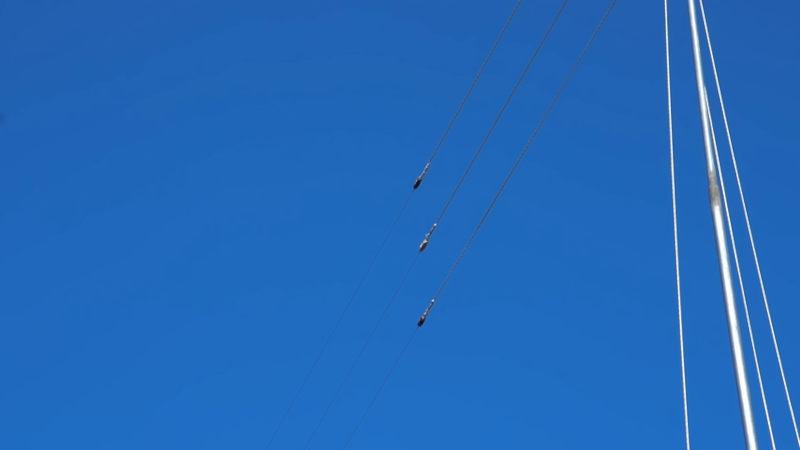
Although the antenna isn’t done, it is already working and looks impressive. There’s a lot of wire, so this probably isn’t a condo-friendly solution. The name of the antenna derives from the three wires, one tuned for 3 MHz, one for 6 MHz, and the other for 9 MHz.
The mechanical construction is impressive, with springs and pulleys. The wire used is actually MIG welding wire which is cheap and durable. Supposedly, the antenna has already performed well with an average receiver, but we didn’t get to hear it ourselves. Maybe in the next video.
If you are looking for more antenna theory, we got you. If height’s got you down, try rising to the occasion.


With one end of each antenna common, I guess the configuration is constrained to bands which are multiples, to avoid standing wave problems.
The only other multi-band antenna I’ve come across was a center-fed dipole with a pair of tuned LC filters, one either side, connecting the longer length only at the lower frequency. I’d hazard a guess that a three band antenna of that type might be possible with two parallel filters, one for each lower band, at the inner section junction? And, yep, there’d be a balun in the middle, to match to co-ax. That was about half a century ago, so details are hazy in the wetware RAM. Why the complexity? The whole wire length is only the length needed for the longest wavelength, and there’s just one feedpoint.
@Erik Christiansen said: “The only other multi-band antenna I’ve come across was a center-fed dipole with a pair of tuned LC filters, one either side, connecting the longer length only at the lower frequency.”
That is called a “trap dipole”. The principle also works on the multiple elements of a Yagi-Uda antenna.
I very much enjoy Mr. Carlson’s videos, but found his 3-6-9 antenna videos lacking in design specifics. One item in particular was his choice of using .035 S6 MIG Wire, which given my research I discovered that, depending on the manufacturer, has an elongation factor of 22% — 28%. Maybe I’m missing something here in my analysis and I’d welcome any feedback or insight anyone might be able to offer me regarding this matter. Also, is there a compelling reason was he chose to end feed it versus center fed? Best regards, de K4SSS
That is pretty much a fan dipole with the coax cable’s outer shield serving as the second “half.” Honestly, the 9mhz wire would be unnecessary as the wire for 3mhz would be an odd multiple at 9mhz and provide a good match.
As the other commenters before me, I’m kind of skeptical on this design – if you say “these are three different wire antennas, and individually they’re tuned to frequencies of 3, 6 and 9 MHz”, then that means you’ve tuned them so the feedpoint impedance matches the transmission line impedance. Awesome! Now, putting these three in parallel leads to, without any mutual coupling, to anything but the same feedpoint impedance.
Now, maybe they were each tuned to 3× the feedpoint impedance or such, but then putting these individually tuned antennas in close proximity over their whole length: that sounds more like a bit of an aperture antenna with gain to the normals of the plane spanned by the three wires. I mean, it’s not like there’s much changing happening in the electrical field between two wires < 2m apart when your wavelength is 33 m (9 MHz), 50 m (6 MHz) or 100m (3 MHz): the field experiences the antenna wires as "one" thicker wire where current can only flow along the direction of the wires.
Is there any EM simulation or analytical result that suggests this works significantly better than just an antenna that's a little too short for a 3 MHz antenna? I mean, that would work reasonably well on both 3 MHz and 9 MHz (odd divisor), and possibly also on 6 MHz.
I'm sure the designer tested this thing – after all, his workbench shows a wealth of mostly obsolete, but still good enough for these "nearly-DC" frequencies, measurement equipment – but I've learned to be very very vary around ham "word-of-mouth" antenna designs. I'd like to know what that testing amounts to. How do you test such things? Against what reference? Certainly not a "my absolutely unbiased opinion after spending 100s of hours on this is that my average receiver works like an above-average receiver, both of whose performances I know by asking the bottom of my heart".
Before I'd invest that amount of material into an antenna, I'd want to have some reasonably traceable results that tell me I'm not having three neighborhood fights, half a month's salary in metal parts and a gigantic lightning house insurance problem for the benefit of a mediocre antenna. I think in 2021, where running a NEC2/eznec, or even a complete 3D FEM simulation on an antenna can be done for free, do we still need to talk about an antenna design before it has proven itself in simulation?
Fan Dipoles are a very similar design (multiple radials attached to a single feed point) and have no issues with impedence matching like you’re describing. Check DXZone or Youtube for multiple people showing these antennas behavior in EZNEC or similar.
-73s
I’m sorry if I sound a bit sharp, but:
Eexcellent! So, this antenna has been simulated? Not just a generally similar one?
Generally the off-frequency wires will have a much higher impedance than the on-frequency wire. Each wire is in parallel Paralleling two much higher impedances with the lower impedance of the wire for the operating frequency does not substantially change the impedance at the feed point. Exactly how much is further affected by the height of the wires, nearby objects such as trees and buildings, and the exact construction of his grounding system including the coax. That is more complex than the three wires themselves and would be best handled by a simulation program or by measurement with some form of antenna analyzer.
I don’t think Mr. Carlson has done either. He has indicated that he’s made provision for adjusting and changing his ground system. My experience is that for receiving in HF bands impedance matching is rather unimportant since most receiver sensitivity is better than the atmospheric noise and other radio interference even on a marginal receiver. Two things have a much more significant effect. Height and to a lesser extent resonance. The selection of lengths for resonance captures wanted signal more efficiently and height gets the antenna above houses and trees that may absorb RF energy. A higher horizontal antenna accepts energy better at an angle just above the horizon than a lower one. The most distant signals (often weaker) will arrive from just above the horizon.
Mr. Carlson achieved fairly good height and that is probably most responsible for his satisfactory results. Many books have been written about antenna design and thousands of variations exist. Almost all have advantages in a few respects but none do everything well.
I would guess that thousands of people have gotten good results with simple wires of random length strung as high as possible on available supports. Mr. Carlson achieved what he wanted to achieve with all the features mentioned in the videos. In addition I am confident he will achieve any future goals with modifications or new antennas.
The improvement over what he had previously was huge or he would not have been so excited about it. There are many ways to refine this antenna but none will provide so great or exciting improvement as this antenna did.
Dang thing fine.
Paul’s channel is a good if you’re new to electronics-Radio…
Once you understand ohms law… time to move on
Ah yes! Good old fashioned condescension. Never enough to report to remove, but always unhelpful and completely irrelevant. What a great example for the community you set. What a ridiculous comment.
OK Einstein, whatever you say.
Better to remain silent and thought a fool than to speak out and remove all doubt.
Thanks for removing all doubt..!
Actually, I believe Warren Masters is somewhat Correct. I was a Patreon member for a while and recently canceled. I found his education in the recent series pedantic and available elsewhere on YouTube in a more direct and better explained format.
You can’t beat a piece of thin rusty steel wire for making a high performance antenna
To be fair, most current would flow in the copper coating, but as soon as that gets any bruise, you’d expose the less inert steel to a copper surface; usually in metal surface treatment, you put on a lesser inert metal (zinc in galvanization) to avoid the main body of metal being corroded in favor of the surface.
I’ve been considering this antenna design. The length is quite long, 1-1/2 wavelengths starting at 3 MHz. Due to space limitations, I would double the Frequencies (1/2 the lengths) to 6-12-18 and start at the 40meter bands and up. This is a receive antenna. A lot of detail is left out in Mr. Carlson’s presentation. What is mentioned is there is no balun, the feed line is 75 ohms. My interpretation is The receiver impedance is not known. The coax may provide some impedance transformation. High impedance on the antenna at points are ok since it relies on voltage and not current for signal reception. 1-1/2 wavelength captures more energy than 1/4 antenna. Thoughts, on to experimenting.
Hi, did you ever try out your 6-12-18 idea? Would that work at all for reception in the AM band?