We wouldn’t go so far as to say “don’t try this at home”, but the way [Troy] brought an expensive (but out of warranty) laptop back to life is interesting, even if it shouldn’t be anyone’s Plan A for repair work.
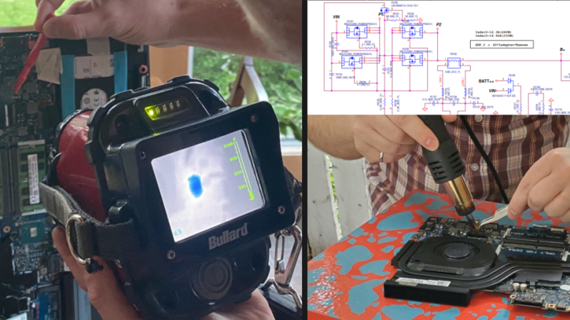
It started with a friend’s Alienware laptop that would only boot to a black screen and get very hot in the process. With the help of a thermal imaging camera and some schematics, [Troy] was able to see that one of the closely-spaced MOSFETs in the power supply appeared to be the culprit. Swapping the power MOSFETs out with replacements seemed a reasonable approach, so armed with a hot air rework station he got to work. But that’s where problems began.
The desoldering process was far from clean, in part because the laptop’s multi-layer PCB had excellent thermal management, sucking away heat nearly as fast as [Troy]’s hot air gun could lay it down. It ended up being a messy slog of a job that damaged some of the pads. As a result, the prospects of soldering on a replacement was not looking good. But reviewing the schematic and pondering the situation gave [Troy] an idea.
According to the schematic, the two MOSFETs (at least one of which was faulty) had parallel counterparts on the other side of the board. This is typically done to increase capacity and spread the thermal load somewhat. However, according to the current calculations on the schematic, these parts are expected to handle about 20 A in total, but the datasheets show that each of the MOSFETs could handle that kind of current easily (as long as heat sinking could keep up.) In theory, the laptop didn’t need the extra capacity.
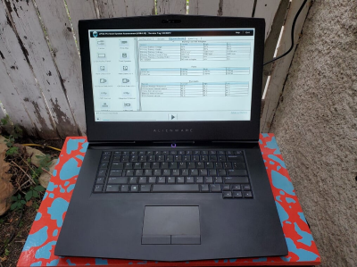
Could the laptop “just work” now that the faulty part had simply been removed? [Troy] and his friend [Mike] were willing to give it a shot, so after cleaning up the mess as best they could, they powered the laptop on, and to their mild surprise, everything worked! Some stress testing with intensive gaming showed that the thermal problems were a thing of the past.
Simply removing a part may not be the best overall repair strategy, but much like shrinking a hot air rework station by simply cutting it in half, it’s hard to argue with results.


I still haven’t replaced the mains-input RIFA cap in the PSU of my BBC model B, which smoked bombed upon switch-on several years ago now (as they invariably and notoriously do). It was only there for EMI reasons anyway. Not quite the same thing.
I’ve quite often repaired a device by just removing the faulty component; especially the old RIFA suppression capacitors (in devices that are infrequently and briefly used, otherwise I’d replace it).
In this case, I wonder why the MOSFET failed in the first place. Without the rest of the schematic, it’s hard to tell what their function is anyway; they seem to be connected anti-series, but the two on the right don’t have any gate resistors, and none of them have gate-source overvoltage protection. Considering the Vgs(max) is 20V, and laptop supplies are generally 19V, that seems like a crappy design. Either I’m reading this wrong (which is entirely possible), of whoever designed this was a complete idiot.
I’m not sure why there needs to be a circuit to disconnect the power supply at all, the battery will have a separate switchmode converter for charging. I think I would have considered bypassing the whole thing.
” they seem to be connected anti-series”
That’s typically done for reverse polarity input protection (the body diodes are back-to-back and can’t conduct).
That is also how you make a bidirectional mosfet power switch, which can double as an ideal diode. That is also typical in battery pack BMS’s when you use common charge/discharge lines. In buck/boost circuits and makes a great bidirectional switch transistor. You can’t do that with bipolars
Also, some high speed switching mosfets applications do not have resistors. They can cause the gate to “ring”. Very tricky stuff in critical switching circuits. I had a pile of over 100 blown mosfets on my bench at one time figuring that out. Mis-commutating while trying to put power into the grid tends to blow the lids off of them.
That MOSFET circuitry is almost certainly part of an “ideal diode” circuit, right out of the applications section of datasheet for something like the LT4359, probably to serve no purpose other than reverse-polarity input protection.
See Figure 6 on page 10 of the LT4359 datasheet: https://www.analog.com/media/en/technical-documentation/data-sheets/ltc4359.pdf
Why did the designers go overkill with the parallel MOSFETs? Probably because some silly engineering team manager declared that the input power reverse-polarity circuit circuit block must dissipate no more than X amount of power.
An ideal diode ain’t bidirectional by the way.
I get a smile thinking of an old laptop, an apple I think. Built especially w low power everything, and thus, no noisy battery-robbing fan, it overheated in their lab. It was a surprising conundrum for them. Somebody rebuilt it with normal components. It got warm enough that NOW, convection caused the fanless thing to flow air… SOLD! And so, it was, sold just that way. Ain’t science wonderful? A happy counterintuitive surprise every now and then.
Taking out components? That’s Muntzising.
Taking out the right components is Muntzing.
Came here for a comment on Muntz,
not disappointed.
https://en.wikipedia.org/wiki/Madman_Muntz
well, you can’t argue with results. I “fixed” a faulty headphones removing the ANC push button that was preventing it to turn ON. It doesn’t compare with the work done with that laptop but yeah… sometimes less is more.
The big question here is how in the world did he get a schematic to a commercial laptop motherboard?
Must be a “planned obsolescence” component was removed.
“Why did the designers go overkill with the parallel MOSFETs? Probably because some silly engineering team manager declared that the input power reverse-polarity circuit circuit block must dissipate no more than X amount of power.”
That should have read:
Why did the designers go overkill with the parallel MOSFETs? Probably because some silly engineering team manager declared that the input power switching / reverse-polarity protection circuit block must dissipate no more than X amount of power.
Data corruption between my brain and typing fingers again. I know that this theory for the apparent over-engineering might sound silly, but in this day and age were every mW saved earns you a brownie point with the environmental awareness team, even if in the scheme of things those mW amount to next to nothing, it’s as good a theory as any. I’ve honestly been exposed to sillier.
I think that the answer is more that the stated maximum current probably isn’t the actual package-limited, in-application, maximum rating, people and often designers misundertand thermal properties in mosfets all the time.
“I think that the answer is more that the stated maximum current probably isn’t the actual package-limited, in-application, maximum rating, people and often designers misundertand thermal properties in mosfets all the time.”
Quoting your post as I don’t know where the comments section dodgy threading is going to poke my reply.
I just looked up the MOSFETs. They are part # MDU1512, a 100A device with an Rds on of 3.4 mR. A single device can handle the input current easily.
Two of those in series gives you 0.0068 ohms and at 330W input (about 17A@19V) about 2W of dissipation.
By putting an additional pair of MOSFETs in parallel as the designers of this laptop have done, the effective Rds on is halved and the total MOSFET dissipation drops by half – a saving of about 1W.
Is 1W saved worth the extra parts?
I have a 2010 MacBook Pro that has an issue with its discrete graphics card that can apparently be fixed by removing it. I can’t use it at the moment and so there shouldn’t be an issue if I fry it while trying to fix it, but I’m still hesitant!!
I had the same problem with a 2011 MacBook pro. I resolved it by removing a resistor that enables the voltage regulator of the discrete graphics card. Much easier and less risky, with the same result, since the card is not powered.
Which instructions did you follow for this can you recall?
Or he could’ve used a preheater to up to 100-150 degrees depending what type of connectors are used on the board. If abs 100, if nylon 150 degrees C. That can make the difference between a sloppy job and an acceptable one. Care must be taken that the heat is spread evenly though, the pcb may warp and bga components may have issues with broken solder balls.
The old joke about repairing something and given them back a bag with the parts that didn’t go back in again.
This approach to electronics repair is my dirty secret. I’ve done it so many times one has to wonder if it isn’t being done on purpose for planned obsolescence.
Confession time.
Fixed a battery powered device the other day which had a short somewhere and had drained the battery completely.
Brand new in box so manufacturing defect. It charges over PoE and I found after removing the battery supply PCB would power up fine over PoE. Whilst probing the supply board my hand slipped, something released the magic smoke and now the whole thing works perfectly. Battery is even holding charge and powering it !!
Saved from the scrap bin.
I knew a stereo repairman that had a coffee can full of defective parts.
If a customer insisted on having the parts that were replaced, he’d reach in and grab a few random parts…
The title of this post is literally how I got my first laptop. The previous owner was selling it to me for parts ($20) and was telling me the story of how it died (thunderstorm with non-surge protected modem line). After turning it on and hearing the hard drive spin up, I turned it off, removed the obviously destroyed modem chip, and voila! A new (to me) laptop.
Earl Muntz would be proud! Legend had it he kept removing components from his companies TVs until they stopped working, and then put the last removed one back again. Supposedly the TVs had really bad receiver selectivity as a result.
I don’t think selectivity mattered much back then. A lot of space allocated for tv, and more when UHF added, but no location had more than a few stations. The point was to allow greater spacing between the channels used in a location.
The tv sets we had in the sixties relied on this. We had some local stations, but the US stations were only viewable very early in the morning. We lost NBC and CBS from the US when the local stations turned on their transmitters in the morning, being adjacent in frequency to those US stations. And then test patterns for too long.
Just looking at a mosfet datasheet and say “hey I can put 20A though it” is a mistake. You need to look though the charts neat the end because often the max current capacity is at a voltage far lower than the max rated voltage of the device.
I would be finding some way to add on another mosfet in parallel someplace.
I’ve read that the Muntz TVs were designed for use in urban areas not far from the transmitter. They had not only poor selectivity, but poor sensitivity and no adjustability — no capability for tuning the IF strip after manufacture. These deficiencies were not much of a problem for the intended market.
Back then, and still today, TV transmitters in a single city were assigned alternate channels. New York City had channels 2, 4, 5, 7, 9, 11, 13. There’s an additional 4 MHz gap between 4 and 5.
Reminds me of a time when I was 6, I took a cassette player apart to see how it worked and then put it back together and it worked but I had parts left over, some adult asked me “What are those?” and I said “Spare parts”.
I sort-of similarly “fixed” an old Mac Powerbook that had a fried firewire chip (literally…where the chip had been was a blackened crater on the logicboard. You could, with sufficient force and determination jam a FW400 connector in backwards, which runs a bunch of current through the wrong way.)
The Mac ran (no FW connectivity of course!), but wouldn’t sleep until I disabled the FW kext by removing it from the /System folder.
Had to remember to do that after any OS update…
Had a similar fault on an HP dv6000 which had smoke gently wafting from somewhere under the keyboard when on.
Bad tantalum capacitor, simply removed it and no more problems!