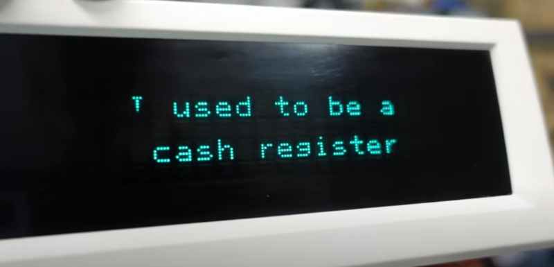
A lot of electronics wind up in landfills, and when [Playful Electronics] saw an old cash register heading for the dump, he decided to give its VFD display a new life as an Arduino peripheral. While you might not find the exact same parts, it is still fun to watch him work through the process, and you might find some tips for doing your own upcycle project next time you see some old tech heading out to pasture.
The project was relatively straightforward since data for the display was available. It is meant to connect via RS232 with a point of sale printer, so working with it is pretty straightforward.
While VFDs aren’t the latest technology, they do work well, especially in bright environments like inside a car. It seems like having an RS232 display like this would be worth something. However, we did find a few units online for sale, they were priced pretty high. We bet there are some caches of surplus somewhere, though.
We can’t help but note that not all VFDs — or any kind of embedded display — are quite this easy to hack. On the other hand, if you want to really hack a VFD, you don’t have to use it as a display.


I saw VFD and thought “variable frequency drive”. Oh well.
My thoughts exactly
And when Hackaday had an article on Variable Frequency Drives, I was disappointed that it wasn’t about a display.
I was wondering about that. In consumer products I’m more familiar with white (actually, “white-ish”, with a slight blue tinge) VFDs which incidentally I tend to find nicer to read – but seem more fragile, because the few I still have in the house are very very dim now, even thought they had not seen much continuous use.
They do have a lifespan and it is not really related much to usage. All tubes slowly leak and the molecules that enter the tube are absorbed by the getter material flashed into the tube during manufacture. Eventually the getter absorbs all it is going to and then the leakage degrades the anode and cathode of the tube. Same failure modes as all other vacuum tubes.
Normally properly produced tubes can be leak proof for decades. The only failure mode I know for these VFDs is that the mostly used segments burn out slowly and get dim. Like on a PACE sat receiver with Sky decoder which wrote “Stand by” on the display when switched “off”. When you changed the volume, there was a bar off all dots lit and you could clearly read “Stand by” in reverse letters. And it’s power consumption dropped from 25W to 24.5W in “Stand by” – probably due to the reduced display brightness.
I love the look of VFD’s that bluey green shade is the best.
That phosphor needs a lower acceleration voltage for a given brightness than some other colors; that’s why it’s popular for VFDs.
Hey! These are still actually used in POS. You’ll have to look up “display pole” for the search term… if they’re clearing out somewhere expect to get some for basically shipping. Otherwise they’re 20-40 in used working condition.
You can search for Logic Controls or UTC as well. Sometimes people will sell them with no idea what they’re called.
Although I’m not sure the VFD are in production currently (maybe from Bematech if they’re still around, they bought Logic Controls line). So they might not continue to be available.
AFAIK Noritake (yes, the dinnerware company) still makes VFDs.
Lol I just made something very similar – https://imgur.com/a/q1kcx7v . connects to the internet on wifi, so I scroll news headlnes, weather, and stock market.
tell me more what you used
just two parts – esp32 dev board and the VFD. I’m going to write up a tutorial about it soon
i have two vfds from logic controls. figured out how to power them and used a usb to serial to connect one at a time to pc
the esp32 aka all wireless connection would be great. also id want to talk to each of these vfds via the same vfd and able to display different things if possible
Great hack ! Takes back to my days at NCR. The early cash registers used nixie tunes then moved to orange plasma displays and then VFD’s. The main displays for the clerk were specialized with some having the words like Cash Tendered/No Sale/etc.. in the displays. The customer displays were generalized being able to display anything that would fit on the display. Some had arrows that would light up to point at stick on words. Lots of displays on eBay under NCR pole display. Very reasonable price.
I donated a similar VFD to the local hackerspace years ago. I stuck a ESP8266 in there and someone else even wrote code that pulls IT news and shows it :) https://labitat.dk/wiki/POS-display
I just foun an old VFD from a cash register in an abandoned place, and was about to google for how to drive it when I found this. Unfortunately, this one is a simple 7+1-segment display of 11 digits, it has one row of 11 pins and one row of 8, and then two pairs of two pins tied together, and no other electrpnics on the board, save for three resistors. So I probably need the correct voltages to drive those…
Post some good, sharp pictures somewhere and drop a link here and we’ll get you up and running with it.
Many of them need about 25V for grids and anodes and a few volts AC for the filament, often depending on the length of the display: 1,5V for a few cm, 3V for 8 to 10cm and 5V for like 15 to 20cm. Of course that is a very rough estimation. Another hint is that the filament should not/barely glow visible. Like in a completely dark room, of course with unlit segments, you can “just think it glows”. I do not know a better description.
If you just have the VFD tube it is quite a challenge to make a driver, for the reason Martin cites. Not really worth hacking unless you also have the electronics to drive it and can just intercept the logic level drive signals. Unfortunately most devices of the era when these were really popular have the necessary power supplies separate from the display and segment drivers, so anything other than a purpose built standalone board is pretty hard to work with.
Maxim makes a line of VFD driver IC’s to serially interface with a uC, such as the MAX6934; it can output 8-76V to the grid, and there’s a few different IC’s in the family that can drive up to 32 segments. I have a few I sampled a long while back on a lark, but haven’t been bothered to buy a cheap Russian VFD on eBay to play around with them.
Noritake specializes in VFD and they have some really nice ones out there. https://www.noritake-elec.com/products/vfd-display-module My SlimDevices SqueezeBox 3 still works (thank you Logitech)… but even when it will not, the VFD in it must find a second use… I guess OLED is the modern challenger to VFD.
Standalone serial VFD displays have always been pricey. Back in the 1990’s I designed an industrial system which is still in use that used a 4×20 0.5″ high character dot matrix alphanumeric VFD. Last time I had to replace the board a refurb was over $700 USD, and the very first new one was over $500 in the 1990’s.
I have one of those, or a very similar one in a box somewhere; mine is identical but black.
I paid like a couple bucks for it at a flea market. They’re used in old POS systems, PC based cash registers etc. It has a serial port but I don’t recall a USB one, have to find it and check. However, I’m pretty sure the display modules (there’s two, one per side) might use standard LCD modules protocols, possibly compatible with the ubiquitous HD44780 and clones. If that’s the case, then one can directly interface to the LCD modules avoiding the RS232 signal conditioning and all that jazz: an ESP32 plus a LCD library and the necessary code to accept connections and drive the modules using one additional pin as chip (module) select would be enough to do pretty much everything without messing with cables.
Nice, i have similiar Projects. Sometimes i found new Items in eBay for a few Bugs.
https://hackaday.io/project/161461-vfd-worldclock-30
https://youtu.be/7UcwMIJwREI
Just small note / correction: [Playful Technology] instead of [Playful Electronics]
Here’s something I made a while back… https://github.com/jim-thompson/m404
The M404 is built around a Futaba M404SD01 VFD module, which are unfortunately hard to come by these days. I was lucky enough to buy four on eBay at $20 each. I’m still looking for projects for the other three.
yeah those large vfds are crazy expensive now. I just ordered a GU140X32F-7703A GU128X32F from china. $39, not cheap but have a VFD addiction at this point.