Probably the most interesting facets of amateur radio in 2021 lie in the realm of digital modes. Using the limitless possibilities of software defined radios has freed digital radio communication from the limits of what could be done with analogue electronics alone, and as a result this is a rare field in which radio amateurs can still be ahead of the technological curve. On of these newer digital modes is FT8 created by the prolific [Joe Taylor K1JT].
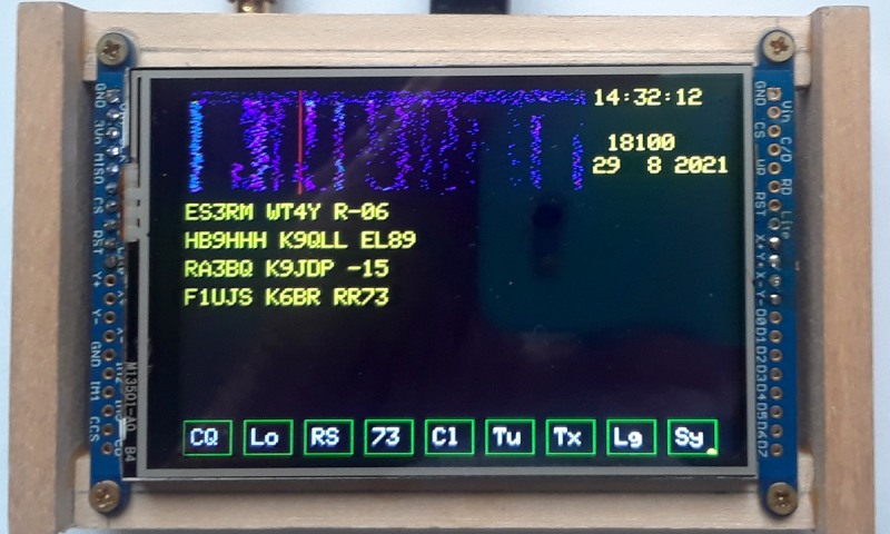
And it’s for this mode that [Charles Hill] has created an easy-to-build transceiver. Its brains are aTeensy 3.6, while the receive side is a Si4735 receiver chip and the transmitter is a Si5351 programmable clock chip driving a Mini-Circuits GVA84 power amplifier with an appropriate filter. The interface is via a touchscreen display. It relies on existing work that applies a patch on-the-fly to the Si4735 receiver chip for SSB reception, and another project for the FT8 software.
The charm of this transceiver is that it can be assembled almost in its entirety from modules. Some radio amateurs might complain that homebrew radios should only use the most basic of components assembled from first principles, but the obvious answer to that should be that anything which makes radio construction easier is to be welcomed. If the 100 mW output power seems a bit low it’s worth remembering that FT8 is a weak signal mode, and given the right propagation conditions the world should be able to hear it despite the meagre output.
We’ve featured quite a few radios using the Si47XX series, which can be made into very tidy receivers indeed.


That itty-bitty waterfall is adorable.
Hmmm… Maybe use an ESP32 or ESP8266 instead of the Teensy 3.6 for control via WiFi. Also stream I2S audio via a codec over WiFi. Now the transceiver can be located outdoors directly at the antenna terminals without any RF transmission line insertion loss. DC power would heed to be run up to the transceiver, or better-yet solar power it. Indoors a PC or laptop will send/receive control data and I2C audio to/from the transceiver using a regular SDR application.
ESP32 and ESP8266 are EMI monsters.. I wouldn’t want one near a sensitive radio receiver.
+1 This is unfortunately true.
It is very hard to keep the 2.4GHz Wifi transmission out of any nearby sensitive analog circuitry..
@jpa said: “ESP32 and ESP8266 are EMI monsters.. I wouldn’t want one near a sensitive radio receiver.”
Really? I’m a Ham with HF/VHF/UHF radios and by following good practices, the ESPs are well behaved RF-wise in my experience. Certainly no worse than any other 2.4 GHz WiFi gear I have. Remember, there is a lot of filtering going on between the HF FT8 radio and the 2.4 GHz WiFi radio.
The schematics is wrong. The 100n decoupling cap must be on the other side of the RFC coil in order not to short most of the RF output to the groud. Also the name of Ricardo Carati PU2CLR is misspelled. Not mentioning using external ADC instead of proper programming.
Overall quite a nice project, but I would wait for some better fork.
I believe the schem placement for the 100n cap is correct.
The cap gives the RF from the V84 chip are return path to ground AFTER passing thru T1 primary.
The 0.1 uF in the supply line after the RFC is the correct place to put it here. It’s not a decoupling cap: it supplies the DC to the output transformer T1. 0.1uF is too large though: its self resonant frequency will be near the transmit frequency.
An external ADC is appropriate here. The Teensy’s two ADCs are busy with the audio at 6400 Hz. Asking them to multiplex to sample the touchscreen at a few dozen Hz is asking for heaps of trouble and pain. A simple external ADC pair dedicated for the touchscreen is cheap insurance.
ok, but this have mesh? what protocol? Can I use this on ism band?
for example PMR+any hand radio ?
this is better comercial device? for example gotenna?
Perhaps you should look up what FT8 is. I’m pretty sure none of your question even apply.
+1
FT8 is a wonderful mode that helps to further automate and dehumanize amateur radio. Bravo. 👏
And now excuse me, I need to finish watching my chess computer playing against itself. Vy73/55
Don’t know how rules are set in your country, but over here radio amateurism is described as experimental radio related research.
True, the days of trying to make contacts by just listening to audio and generating audio (in this I generalize and describe CW as audio due to the way you listen to it) were more labor intensive. However, there is so much noise in the air that over here listening to audio is a pain in the a** and almost impossible.
Modes like this (even automated) qualify for the experimental nature without the pain of listening to all kinds of noise all day. This way you still can look at propagation for example without generating tinnitus.
“Don’t know how rules are set in your country, but over here radio amateurism is described as experimental radio related research.”
Interesting. “Experimental”, “research” aren’t exactly terms that I would associate with a mode that’s sole purpose seems to be pushing people’s egos.
What is gained trough FT8? How does it serve society? What do hams using it learn on the technical side? Which skills can be developed through its use?
What happened to the ham spirit?
What happened to “we” (sense of community)?
In FT8/FT4, you can’t even say “Hi!” or learn about other people’s names, culture or personality. Even in other sports, people do at least handshake or great each others.
All that’s left in FT8 are numbers (calls) and statistics. How can someone even say it doesn’t dehumanize, at all?
Well said. This “never FT8” is getting tiresome. I’ve been a ham for over 54 years now. I grew up with AM and CW. I welcomed SSB. I welcomed AMTOR. I welcomed PSK31 et al. And yes, I welcomed FT8. If not for FT8, we would have lost a lot of hams during this solar minimum. Most of the time, FT8 was the only way to make any kind of DX contact. I’ve been more active since I dicovered FT8 than I have in years. I’ve made more contacts since I got on FT8 in 2017 than I made in all the years before. It has completely revitalized ham radio for myself and many thousands of others. If you don’t like it, don’t operate it. Unfortunately, OM, spark is illegal these days.
I like some of the stuff Silicon Labs makes but if you ever design a PCB with one of their chips then be prepared for it to be a onetime deal because they churn out new chips and abandon the old ones on a regular basis. This makes any significant time investment a waste because even if you give your design away, nobody can use it after mere months.
Using chips from Silicon Labs only makes sense if you are a big business prepared to buy many thousands of them.
The chips mentioned here were introduced in 2012, and except for chip shortage, are still available.
Silabs has divested its Infrastructure and Automotive Businesses. The SI4735 and SI5351 are now sold by Skyworks.
Yup, Skyworks now owns the venerable Si570/Si571 clock generators too. Popular chips for RF hombrew, and far better phase noise/jitter specifications compared with the SI5351 – for a price.
I wonder how hard it would be to modify this to do CW and SSB?
Jerry Kaidor said: “I wonder how hard it would be to modify this to do CW and SSB?”
It’s fairly simple, just load AM\CW\SSB Si4735 compatible SDR transceiver firmware into the Teensy micro-controller instead of the FT8 SDR firmware. You will probably also want to add a rotary qudrature-encoder as a tuning knob. See [1] & [2] for a couple of examples.
*References:
1. Teensy 4.0 Convolution SDR
https://www.youtube.com/watch?v=dm-YjUTcQT8
2. DD4WH / Teensy-ConvolutionSDR
https://github.com/DD4WH/Teensy-ConvolutionSDR/blob/master/Teensy_Convolution_SDR.ino
First!
Although the Adafruit module is currently in stock, they are saying the si5351 itself is tough to get but the MS5351M is a direct substitute
I put no stock into what 80% of what hams say, (i am licensed, was at 12 and now at 50) im all for building stuff, this is great. any ham who says it has to be core components is probably talking on a $2,000 radio say can you hear me? and thats their life, good for them. The life here is have fun, make stuff, have fun.
Agree 100%. Complying with “homebrew radios should only use the most basic of components assembled from first principles” for an SDR transceiver using digital modes built from scratch is not a project many hams who are, unfortunately, mainly “appliance operators” could handle. IMO, ALL homebrew electronics projects, not just ham radio ones, should try to use the plethora of very inexpensive and highly capable surface mount component populated modules whenever possible.
I read a funny fictional story in a ham magazine once, about how a guy decided to homebrew from scratch – mining the copper, searching beaches for silicon, etc.
Actually, not that funny.. I can usually build from a parts kits but all this micro–teensy-programming bs might just as well be easier melting sand into silicon glass to me! – Kit it and sell it and I and 1000’s others will buy it!
Any idea where to find that article? I am a funny STEM advisor. Wb2tev club buzzards bay ma
Neat!
On a related note, this guy’s software made it very easy to throw together an FT8 transceiver with what I had laying around my desk:
https://github.com/agustinmartino/wsjt_transceiver
Good stuff!
Why not use Teensy 4 which is much faster than Teensy 3, in order to bypass the sample rate limitation? Pocket Beagle, or Raspberry Pi Zero with a suitable ADC, might be other possibilities that compute pretty fast.
The T4 still has only two ADCs. How would you propose to sample two audio channels at 6400 Hz AND two touchscreen channels at the same time?
Use a better display with XPT2046 touch controller
Well if my scummy Atmega328P running at 20MHz with only 1x ADC can sample I/Q data at 8812 for only 82% CPU load using a single ADC, the Teensy should cream it!
Read all about this simple 5W SDR transceiver design here:
https://github.com/threeme3/usdx
According to https://www.pjrc.com/teensy/techspecs.html all of the teensy3 and teensy4 models have 2 converters, though lots of analog input pins. 6400 hz (or 8 khz) is pretty slow so so multiplexing an a/d might work. However, the t3 has 13 bit converters while t4 has only 10 bits. I wonder why they did that, and if that is the real issue that led the designer to choose the t3.
Another alternative might be the pocket beagle, which has 12-bit converters (8 inputs, not clear how many separate converters) according to this: http://www.righto.com/2017/12/hands-on-with-pocketbeagle-tiny-25.html
The realtime coprocessors run at only 200 mhz but maybe the DSP stuff can be done on the application processor, which runs at 1 ghz.
I tried replicating the transmitter part of this project for VHF (2m band), you can save yourself the hassle if you had the same idea. While the output spectrum of the Si5351 looks okay(ish) on HF frequencies, anything higher than say 50 MHz is totally unusable. If it would just be a square wave it would be feasible to get rid of any overtones using a low pass filter, but with lots of little signals spaced only kHz apart of the configured frequency, filtering is not really an option. Bummer..
It’s easy to make the Si5351 produce an unhealthy amount of jitter and spurs at VHF, but it’s equally easy to make it clean too: From their AN619, “make the output Multisynth divide ratio an integer. If possible,
make both output and feedback Multisynth ratios integers”
Then you’ll be limited by the quality of your frequency reference, and you’ll want a OCXO.
Thanks for the pointers, I tried using integer-only frequency synthesis, but this did not solve the problem. I’m using the Adafruit Si5351 breakout board which has a generic 25 MHz crystal on it. I didn’t expect it to be accurate or temperature stable in any sense, but am suprised by the amount of jitter I get. I have a 26 MHz OCXO laying around, I’ll try with that later. It has a 5v square wave output though, so I’ll have to add some signal conditioning circuitry.
Interesting. I use QRP-labs’ OXCO and Si5351 synth, but I have that Adafruit breakout too. I’ve never compared the two.
Can you quantify the spurs you observe, and list the register setup you use? I’d like to try to replicate the result.
I don’t have the exact register values handy as I used a library to compute them, of course I could read them back if you would be really interested, but for instance using the following multipliers I got an ugly signal using the Adafruit board:
PLL = 25 MHz * 35 = 875 MHz
f_out = PLL / 6 = 145.83 MHz
Would be great if you could try to replicate this with your Adafruit board and your QRP-labs Si5351 OCXO setup.
Quantifying the spurs would be difficult as I don’t have a scope, I just looked at the spectrum using an rtl-sdr. Not very scientific, I know.. What I saw was a lot of frequency spikes over a span of about 1 MHz. I took care not to overdrive the rtl-sdr.
For the record, I ordered the QRP-labs SI5351 synth with TCXO option and tried it, It behaves way better with the same settings. Stable without spurs. So apparently there is something wrong with my Adafruit board, or the Adafruit board in general.
Thanks for following up. I’m sorry I dropped the ball: the hardware is a couple of layers deep in cruft here, and I have not excavated it yet. It’s still on my ToDo list though, and I’ll report back here when I do get to it…
I can’t get the link to work.
The project has been removed from github, does anyone have a copy ?
If you go to github and do a search for pocket ft8, you’ll find it. (I just did :)
Ah, found it now. I’ll be in the Shame Box if you need me :)
Here is a zip-file for the project “Pocket FT8”:
http://oz1bxm.dk/notes/Pocket_FT8_Publish_1.zip
Updated github link..
https://github.com/Rotron/Pocket-FT8
Github link 404’s for me.
Weak signal is not equivalent to low power (QRP)
It’s small, mean and clean! :-) I like it! :-)