A Raspberry Pi-based COVID Green Pass validator verifies a QR code on a phone.

COVID Green Pass Validator With Raspberry Pi

It seems like every nation is dealing with the plague a little differently. In June, the EU instated a COVID Green Pass which comes in the form of a paper or digital QR code. It was designed to grease the wheels of travel throughout Europe and allow access to nursing homes. As of early August, the Green Pass is now required of those 12 and older in Italy to gain access to bars and restaurants, museums, theaters, etc. — anywhere people gather in sizeable groups. The Green Pass shows that you’ve either been vaccinated, have had COVID and recovered, or you have tested negative, and there are different half-lives for each condition: nine months for vaccinated, six for recovered, and just forty-eight hours for a negative test.

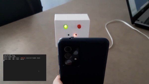
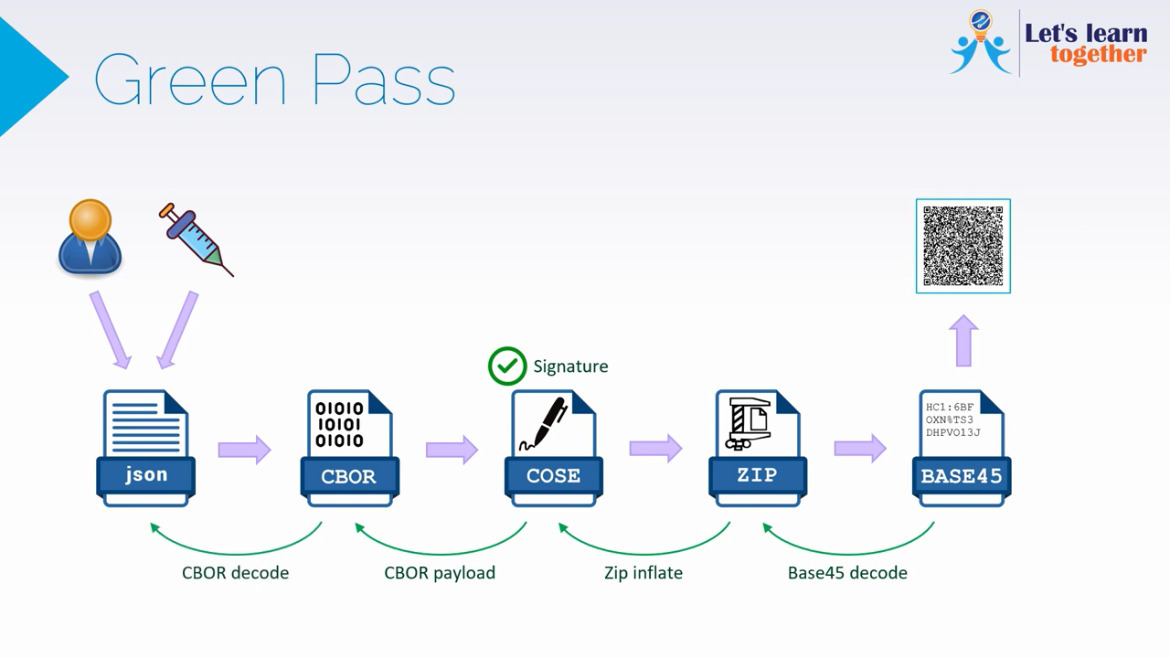
[Luca Dentella] has built a Green Pass validator using a Raspberry Pi and a Raspi camera. Actual validation must be done through the official app, so this project is merely for educational purposes. Here’s how it works: the user data including their status and the date/time of pass issuance are encoded into a JSON file, then into CBOR, then it is digitally signed for authenticity. After that, the information is zipped up into a base-45 string, which gets represented as a QR code on your phone. Fortunately, [Luca] found the Minister of Health’s GitHub, which does the hard work of re-inflating the JSON object.

[Luca]’s Pi camera reads in the QR and does complete validation using two apps — a camera client written in Python that finds QRs and sends them to the validation server, written in Node.js. The validation server does formal verification including verifying the signature and the business rules (e.g. has it been more than 48 hours since Karen tested negative?) Fail any of these and the red LED lights up; pass them all and you get the green light. Demo video is after the break.

Are you Canadian? Then check this out, eh?

Continue reading “COVID Green Pass Validator With Raspberry Pi”

The Simplest FT8 Transceiver You’ll Ever Build

Probably the most interesting facets of amateur radio in 2021 lie in the realm of digital modes. Using the limitless possibilities of software defined radios has freed digital radio communication from the limits of what could be done with analogue electronics alone, and as a result this is a rare field in which radio amateurs can still be ahead of the technological curve. On of these newer digital modes is FT8 created by the prolific [Joe Taylor K1JT].

And it’s for this  mode that [Charles Hill] has created an easy-to-build transceiver. Its brains are aTeensy 3.6, while the receive side is a Si4735 receiver chip and the transmitter is a Si5351 programmable clock chip driving a Mini-Circuits GVA84 power amplifier with an appropriate filter. The interface is via a touchscreen display. It relies on existing work that applies a patch on-the-fly to the Si4735 receiver chip for SSB reception, and another project for the FT8 software.

The charm of this transceiver is that it can be assembled almost in its entirety from modules. Some radio amateurs might complain that homebrew radios should only use the most basic of components assembled from first principles, but the obvious answer to that should be that anything which makes radio construction easier is to be welcomed. If the 100 mW output power seems a bit low it’s worth remembering that FT8 is a weak signal mode, and given the right propagation conditions the world should be able to hear it despite the meagre output.

We’ve featured quite a few radios using the Si47XX series, which can be made into very tidy receivers indeed.

Making Linux Offline Voice Recognition Easier

For just about any task you care to name, a Linux-based desktop computer can get the job done using applications that rival or exceed those found on other platforms. However, that doesn’t mean it’s always easy to get it working, and speech recognition is just one of those difficult setups.

A project called Voice2JSON is trying to simplify the use of voice workflows. While it doesn’t provide the actual voice recognition, it does make it easier to get things going and then use speech in a natural way.

The software can integrate with several backends to do offline speech recognition including CMU’s pocketsphinx, Dan Povey’s Kaldi, Mozilla’s DeepSpeech 0.9, and Kyoto University’s Julius. However, the code is more than just a thin wrapper around these tools. The fast training process produces both a speech recognizer and an intent recognizer. So not only do you know there is a garage door, but you gain an understanding of the opening and closing of the garage door.

Continue reading “Making Linux Offline Voice Recognition Easier”

front view of a purple acrylic slide rule with white ink scale markings.

Design And Build Your Own Circular Slide Rule

You have to really like slide rules to build your own, including the necessary artwork. Apparently [Dylan Thinnes] is a big fan, based on this project he began working on a few months back. The result is a set of algorithms that automatically generates most of the scales that were common on slide rules back in the day. For example:

K       Cubic scale, x^3
A,B     Squared scale, x^2
C,D     Basic scale, x
CI,DI   Inverted scale, 1/x
CF,DF   Folded scale, x*pi
LLn     Log-log scales, e^a*x
LL0n    Log-log scales, e^-a*x
L       Log scale, log10(x), linear
S       Sine and cosines scale, sin(x)
T       Tangent scale, tan(x)

If you’ve ever tried to manually draw an axis using a computer program — attempting to automatically set reasonable tick marks, grids, and labels — you can appreciate that this is a non-trivial problem. [Dylan] tackled things from the bottom up, developing several utility functions that work in concert to iteratively build up each scale. One advantage of this approach, he says, is that you can quite easily build almost any scale you want. We’re going to take his word on that, because the project is not easily accessible to the average programmer. As [Dylan] notes:

At the moment it’s still a library w/ no documentation, and written in a relatively obscure language called Haskell, so it’s really only for the particularly determined.

The project is published on his GitHub repository, and sample scales and demo program are available. Without knowledge of obscure languages and being only mildly determined, one can at least generate some sample scales — just downloading the Haskell environment, a few dependencies, and clone [Dylan]’s repository. The output is an SVG file which can be scaled to any desired size. In this follow-up Reddit post he discusses the fabrication techniques used for the acrylic circular slide rule shown in the lead photo.

It’s always been possible to make your own slide rules using pre-generated artwork — for example, the Slide Rule Museum website has a slew of various scales available in graphic format. But if you want to make a custom scale, or make one of that’s meters long, check out [Dylan]’s project and give it a whirl. For another take on making slide rules, check out this project that we covered last year.

A Promising Start For The Doritos Space Program

Rocketry is tricky stuff, but as long as you’re not trying to get into space, the whole idea can basically be boiled down into a simple concept: if you put enough thrust behind it, anything can fly. At least, for awhile. It’s this basic premise that allows what hobbyists sometimes refer to as “Odd-Rocs” fly; these unusual objects might not be ideal rockets, but put a big enough motor in there, and it’ll get off the pad.

Recently, [concretedog] thought he’d try putting together his own oddball rocket, and set out to modify a Doritos STAX tube for powered flight. There’s plenty of precedent for turning Pringles tubes into rockets, but of course, that’s hardly surprising. After all, what’s a rocket if not a strong and lightweight cylinder? But the rounded triangular shape of the STAX tube promised to be an interesting change of pace. Plus it looked cool, so there’s that.

Turning the snack container into a rocket was actually pretty straightforward. To start with, [concretedog] sketched around the outside of the tube on a piece of paper, and then took a picture of that with his phone. That image was then brought into Inkscape, and turned into a vector file that he could fiddle around with in CAD.

Between the thin plywood cut on his laser and PETG loaded into his 3D printer, he was able to come up with a strong enough motor mount to take an Estes D12-5. He then created some fins to glue on the side, and a triangular nosecone. A simple recovery system was installed, and the whole thing was finished off with a Doritos-appropriate orange and black color scheme.

The unusual shape of the rocket meant simulating its flight characteristics on the computer wouldn’t work without custom software, so [concretedog] had to use the old school method of checking stability by swinging it around in a circle on a string. After trimming it out so it would orient itself properly on the tether, he was fairly sure it would fly straight under power. Sure enough, the video below shows the nacho cheese flavored rocket streaking skyward with impressive speed and stability.

It’s far from the most advanced model rocket we’ve seen recently, but we really appreciate the simplicity of this build. It’s a great reminder that fun doesn’t have to be high-tech, and that by following some basic construction principles, you can knock out a safe park flier rocket on a weekend.

Continue reading “A Promising Start For The Doritos Space Program”

Embrace The New, But Don’t Forget The Old

We were trading stories of our first self-made PCBs in the secret underground Hackaday bunker, and a couple of the boards looked really good for first efforts. Of course there were mistakes and sub-optimal routing, but who among us never connects up the wrong signals or uses a bad footprint? What lead me to have a hacker “kids these days have it so easy” moment was that all of the boards were, of course, professionally fabbed with nice silkscreens. They all looked great.

What a glorious time to be starting down the hardware path! When I made my first PCB, the options were basically laying down tape, pulling out the etch resist pen, or paying a bazillion inflation-adjusted dollars for a rapid prototype board. This meant that the aspiring hacker also had to have a steady hand and be at least casually acquainted with a little chemistry. The ability to just send your files out to a PCB house means that the barrier to stepping up your hardware game from plug-them-together modules is lower than it’s ever been.

But if scratching or etching your own PCB out of copper plate is very hands-on, very DIY, and very low-tech, it’s also very fast in comparison to even the most rushed service. Last weekend, I needed a breakout board for some eight-pin SOIC H-bridge chips for a turtle robot project with my son. Everything was hand-soldered and hot-glued in a Saturday afternoon and evening, so there was no time for a PCB order. A perfect opportunity for the Old Ways™.

We broke out a Sharpie, traced out where the SOIC pins would land, connected up the grounds, brought the signals out to friendly pads, and then covered the rest of the board in islands of copper just in case we’d need any prototyping space later. Of course, some of the ink lines touched each other where they shouldn’t, but before the copper meets the etchant it’s easy enough to scrape the spaces clear with a pin. The results? My boards look like they were chiseled out by a caveman, but they worked. And more importantly, we got it done within the attention span of a second grader without firing up a computer.

So revel in your cheap offshore PCB factories, hackers of today! It’s a miracle that even four-layer boards come back within a week without breaking the bank. But I encourage you all to try it out by hand as well. For large enough packages and one-offs, full DIY absolutely has the speed advantage, but there’s also a certain wabi sabi to the hand-drawn board. Like brush strokes in residual copper.

A tiny solar-powered robot that even works indoors

Tiny BEAM Robot Smiles Big At The Sun

What have you been working on during the Great Chip Shortage? [NanoRobotGeek] has been living up to their handle and building BEAM robots that are smaller than any we’ve seen before. What are BEAM robots, you say? Technically it stands for Biology Electronics Aesthetics and Mechanics, but basically the idea is to mimic the movement of bugs, usually with found components, and often with solar power. Here’s a bunch of tutorials to get you started.

The underbelly of what might be the world's smallest BEAM robot.
This was before the large, flat storage capacitor came and covered everything up.

This here is an example of a photovore or photopopper — it moves toward light using simple logic by charging up a capacitor and employing a voltage monitor to decide when there’s enough to run two tiny vibration motors that make up its legs and feet.

[NanoRobotGeek] started in a great place when they found these 25% efficient monocrystalline solar panels. They will even make the bot move indoors! If you want to build one of these, you can’t beat [NanoRobotGeek]’s guide. Be sure to watch it toddle around in the demo video after the break.

We love to see people work at all different scales. Last time we checked in with [NanoRobotGeek], they had built this solar-powered ball-flinging delight.

Continue reading “Tiny BEAM Robot Smiles Big At The Sun”