Supercapacitor technology often looks like a revolutionary energy storage technology on the surface, but the actual performance numbers can be rather uninspiring. However, for rapid and repeated charge and discharge cycles, supercaps are hard to beat. [Tom Stanton] wanted to see if supercaps have any practical use on e-bikes, and built a DIY electric motor in the process.
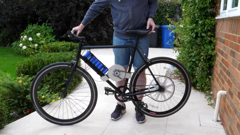
One of the problems with supercaps is the rapid voltage drop during discharge compared to batteries, which can limit the amount of usable energy. In an attempt to get around the voltage limitation, [Tom] built his own axial flux motor for the bike, using 3D printed formers for the coils and an aluminum rotor with embedded magnets. He expected torque to be severely limited, so he also machined a large sprocket for the rear wheel. He built a capacitor bank using six 2.7V 400F supercaps, only equivalent to the capacity of a single AA cell. Although it worked, the total range was only around 100 m at low speed. When he hooked the motor up to a conventional battery, he did find that it was quite usable, if a bit underpowered.
The controller for the DIY motor was not capable of doing regenerative braking, so he fitted the capacitors to another e-bike that does have regenerative braking. Using this feature, he was able to reclaim some power while slowing down or going downhill. Since this type of charging cycling is what supercaps are suited for, it worked, but not nearly to the level of being practical.
[Tom]’s projects are a popular feature here on Hackaday, and he has also experimented with supercaps in RC “rockets” and a flywheel for energy storage on the same bike.


8 is the new 6?
Did you mean – 88?
In one aspect supercaps are similar to batteries: they really don’t like being overcharged. And because the capacity is smaller, overcharging happens faster and easier. Better have some overvoltage shunt setup in place, unless the regenerative setup can truly cut off when full. Most BLDC drivers leak current back into battery if the motor is spun fast enough, even if software keeps the FETs off (conduction through parasitic diodes).
This is called regenerative braking, a bunch of ebikes (I wouldn’t say all, but a lot) use this feature, it extends the range by recharging the battery with this current, it’s much better than having the FETs off (conduction diodes are pretty bad) or shorting the motor leads (you get lower heat generation from the good FET rdson, but you also waste that power and the braking is very uncontrolled and slow)
Yeah, regenerative braking is great – until your capacitors are full :) I was talking about what to do after that.
But there are efficiency losses, so how can you put more energy into the caps than you started with?
If you were fully charged and you started at the top of a hill, maybe. But once you use some energy you will only ever get less back.
This is an extremely real problem. I had to undercharge my DIY scooter each night so I could ride downhill from home to work in the morning. The regen brake was the only brake there was (except the original stomp brake) :D
Then latter I had an original Xiaomi scooter which I didn’t bother to not fully charge but I still could feel during every morning ride downhill when the regen brake turned off and I suddenly had to press the brake lever farther to engage the mechanical disc brake.
There is no “maybe”. Its a huge problem for those of us that live in hilly terrain, with unlucky charging locations.
Yeah normally a good controller would have multiple braking systems, once the battery is full, burn it in a brake resistor for example.
OH NO!!!!!! It just started to rai……………………
+1
+1
Wonder if you could do a hybrid supercap / battery system. The supercaps would be a good place to dump the energy from regenerative braking while the batteries would get you home. It would take some electronics.
Thinking out loud here: Use an “ideal diode” circuit on the input of the motor controller, to select supercap or battery as the source automagically. Put a boost converter with an output voltage above the battery voltage on the output of the supercaps so the voltage does not fall off as quickly. Use a charge controller to protect the supercaps from overcharge. Assuming the supercaps and battery are both charged, when you start out, the supercaps power the motor controller until they are depleted and the boost converter shuts down, then the battery takes over. When you brake, energy from the regenerative braking re-charges the caps until the next acceleration.
Worth the effort? dunno…
Yes, this is possible. Several companies are researching this technology to see if it is viable to make regenerative braking more efficient and less hard on the batteries.
I don’t recall the specific company, but their slogan was ‘we’re not about kilowatt-hours, but about megawatt-seconds’.
This idea has been around since the time when sizable supercaps were theoretical. Back then lead acid was the main battery for diy electric vehicles, and the thinking was that you could also extend the life of your batteries with supercaps.
Obviously to have a useful working voltage rating from super caps, you would have to link them in series which reduces the Farad rating. Then connect them in strings just like a Lipo pack. 6 caps is just not enough. If all of them are in series, only 16V with as said, the collective energy capacity of a AA. Pretty weak! Bring the whole system up to around 24V or higher and give it the capacity of about 24 or more AA’s at over 20V then might have something. Another issue is the design of the motor, it needs something on the other side of the rotor, too much energy loss the way it is now. It’s just like any other electrical circuit, it has be closed for power to flow. There is no means of concentrating magnetic flux behind he coils or feeding energy into the open side. He needs to use half of the copper in those coils in a set of coils on the other side of that rotor. I think He worried too much about making it thin and didn’t consider a design that would make the best use of the materials and available electric power capacity.
You could solve some of the series string problem with the boost converter mentioned above. It would probably be worth working with set of 2 caps in series and paralleling several sets. With 1 cap, it seems like the voltage would not have to discharge much to be below what would be a sane operating voltage for a boost converter. 2 would be a little better.
The capacitance is divided by N, but the energy capacity which is what matters in the end does multiply:
U(n) = 1/2 × (C/n) × (n×Vmax)² = n × 1/2 × C × Vmax = n × U
(In other words, if you charge a bunch of capacitors in parallel and then connect them in series, the energy doesn’t disappear)
Are you sure he didn’t use a FLUX CAPACITOR?
I wonder how much current you’re generating in the chain as the motor magnets spin past it.
:)
Is that why some ebike designers have used belts? Abandoning decades of advances in chain technologies….
Hey Tom, I think that is sort of an axial flux motor. If you can find a way to get the coils on both sides won’t you get more torque? I mean is places your magnets inside a solenoid with more uniform fields. Not a motor guy. Just a hunch.
Also one would want to guide the magnetic field so it doesn’t simply close through the air, where no torque is generated. Building a proper stator with some highly permeable material would do wonders for that motor.
That’s just one of his quick prototypes,if he can make up to 48-52 v,10-15 amps supercar battery will be big difference;!
With such a short range maybe it’s not practical if you think of it as a powered vehicle. But perhaps in a very hilly terrain it would be great for providing assistance on the up-hill parts while re-charging on the downhill ones. Think of it more as a terrain flattener.