[Applied Procrastination] is in the business of vertical ferrofluid displays, but struggles somewhat with the electromagnets available off the shelf and the proliferation of wiring that results. [Carl Bugeja] is in the business of making PCB coils, both with rigid and flex PCB substrates, so when the opportunity for a collaboration arose, [AP] jumped at the opportunity.
As [Simen from AP] mentions in the video after the break, they had considered using a large PCB with embedded coils for Fetch their ferrofluid display unit, but the possible magnetic field was just too weak, and attempting to crank up the amps, just overheats them. Some improvements were made, first sticking the coil PCB to a small disk of ferrous metal, which doubled up as a handy heatsink. Next, he tried adding a permanent magnet, which added a bit of bias field. Alone this was not enough to hold the ferrofluid in place, but with the coil powered, it was starting to look encouraging.
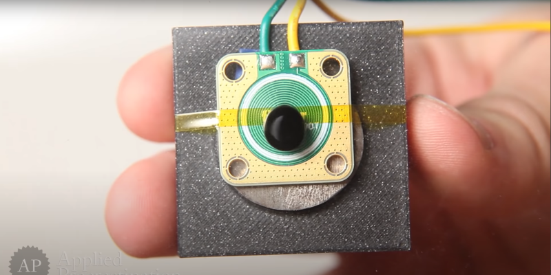
Much more progress was made when [Carl] sent over a new design of his, a 12-layer PCB coil. This obviously had a much larger field, but still not enough without the extra boost from permanent magnet.
[Simen] currently doesn’t think the PCB approach is quite there yet, and is looking for help to source PCB-mounted electromagnets of the wired variety. We would imaging prototyping with such a large 12-layer PCB would be rather prohibitively expensive anyway.
[not tip thanks]


[Applied Procrastination]
[AP]
[Simen from AP]
[Simen]
[Carl Bugeja]
[Carl]
pick one and stick to it?
It’s a collab between two people of which one person is in a group with another person who wasn’t directly involved with said project. So to give proper credit they kind of need to specify specific people. In either case it’s not that complex nor necessary to understand the project.
I commend the PCB approach, but maybe thinking even further outside the box would help here. As far as an electromagnet is concerned, all that matters is how much current density you can push through a small enough volume. Increasing the number of turns at the expense of conductor size means no change in the overall field. At the same time inductance scales as N². If you have a sufficient source of current, you might be better off increasing conductor size. For that it’s hard to beat the Bitter plate design which is used in ultra high field electromagnets (when superconductors become useless):
https://en.m.wikipedia.org/wiki/Bitter_electromagnet
While construction is not as simple as the PCB version, some creative use of a laser cutter (or photoetching if you start hitting production volumes) can be used to make less powerful designs.
I understand the reasoning behind the PCB approach though: assembly time is independent of the numbers of coils. In that case, it might be possible to at least double the field strength by bringing the Bitter plate design to the PCB. Ditch the traces and make each layer an annulus with a thin sector cut out, and connect the annuli in each layer to form a helix.
I was looking at the Bitter plate and wondering what the hell are all those holes for, then after a bit of searching I found out that high pressure water is pumped through all the plates at 45 miles per hour ( ~20 m/s ) to stop them from melting.
(ref: https://youtu.be/tBz6jVC-Gg4?t=251 )
Never heard of them before, interesting stuff, thanks.
Most people simply doesn’t realize that controlling magnetic field is the gate way to space time control and that’s not scifi!
so ferrofluid can only help to see the unseen ! +1
Oh, we know! Trust me, we know.
I trust you but I still don’t know.
You trust Elliot????
(running from room, screaming)
j/k
He knows something I don’t. I am borh suspicious or curious.
I have just clicked his profile link. I feel somewhat embarrassed and star struck. I am a mere lurker on the site and don’t understand most of it.
I am hoping one day it all starts to make sense.
There are some brilliant minds here.
( it’s a complex topic so that can only be a glance of many century of archives ^^)
I simply think at reactance, with inductance or capacitance you can simply control the state of your circuit at time that could not be now but related some how, by the way the lines of a magnetic field that we can see with ferrofluid are just
the the spin of electron which become polarised… so what we see is always electrical not magnetic further more we can see pattern in physics like the analogy between light decay intensity and gravity strength they both behave proportionally to the inverse square of the distance of reference … light is electromagnetic by nature (boson/fermion) gravity not quite but all falling object really weight something measurable only when they touch the ground and there it’s electrical again Neil Bohr atone architecture… ( it’s sim that all body fall at the same space / time speed not tested by my own but it sim like light is always measured at the same speed no matter the frame of reference …) may be we can see a big picture may be not… but magnetic for me is always something out of space and time it’s always a causal measurement (we are always involved… may be in time ? maybe in space ?) , so in conclusion magnetic strength is always measured through a consequence of electricity polarisation.
sorry for this long text but we are all there curious and deeply in love with god, universe law, world physics, light whatever what we are… its always the same things… us ^^
https://en.wikipedia.org/wiki/Liquavista from 2006 have oil electric Video black-white technology.
not static but video
Seems to me to be the absolute least energy efficient display technology possible. What is the use case for something like this?
Beauty! (and general hackery)
You tempt me to make a 7 segment flamethrower.
I agree it may be essentialy useless from a practical standpoint. From a learning and fun standpoint it is as useful as any other project.
Instead of using 12 layers, why not use 6 layers (probably a lot cheaper) and then stack 3 of them giving 18 layers? And put a soft iron core through the lot (an M5 bolt though a hole?) which will also hold them together. And if that doesn’t work, add another PCB to the stack.
The main driver for testing alternatives to normal electromagnets is to reduce complexity (or cost). I’d definitively want to try something like that just for fun, but normal electromagnets are still by far the best option for large vertical displays like Fetch.
I didn’t do the math, but did you guys consider using soldering paste to further thicken traces for 2 layer PCB? it could help increase current and also help radiate more heat. very nice project tho
Why not use a solid copper that have been bent to shape? Your losses come from the resistance of your coils. Making them much thicker means you can drive the same magnetic field with less losses and a much lower voltage. Then add kapton tape on both sides to electrically insulate it. You can buy copper bars fairly cheap and make a rig to bend them yourself.
I like the Bitter magnet comment. The difficulty then transitions to making a high current low voltage DC drive for a single (or few loops ) pcb coil (Al substrate pcbs could be nice here). This electronics then has to sit at the back of each coil to keep the resistance only that of the actual loop. Would feeding the loop with a capacitor to make an LC low pass filter with a mosfet bridge providing pulse width modulation work here? (Eg. a class D amplfier for controlling a speaker). The on-resistance of the mosfet will be the difficult part as well as getting the cutoff frequency of the LC filter low enough to become practical (adding a ferromagnetic core will help, the ferrofluid itself will also help).
I can imagine this quickly becoming a nasty source of em emission though.