When we were kids we rode bicycles without pads and helmets. We drank sugary drinks. We played with chemistry sets and power tools. We also built things that directly used AC line current. [Mike] remembers and built one, presumably more to discuss the safety precautions around things that can shock you and not entice you to duplicate it. He calls it The Retro QRP Widowmaker, if that’s any kind of a hint. (Video of this unsafe transmitter also embedded below.)
The design showed up from time to time in old electronic magazines. Built on an open board and with no ground wire, the radio didn’t need a complex power supply. This wasn’t limited to transmitters, either. Some TVs and radios had a “hot chassis.” That’s why we were taught to touch an unknown chassis with the back of your hand first. A shock will contract your muscles and that will pull your arm away instead of making you grab the electrically active part.
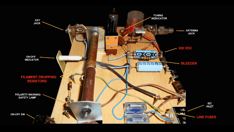
For safety’s sake, [Mike] used an isolation transformer to keep from having a disaster. A big resistor drops a lot of voltage to supply the tube in the circuit. There was a neon bulb to indicate if you have your plugs the wrong way around making things dangerous.
We enjoyed [Mike’s] excellent code using an old J-38 style key. Not everyone uses a paddle or a keyboard. Nowadays, you don’t need high voltages for little transmitters. Also, $50 today is probably worth less than $10 was back then. If you have a hankering for vintage gear, try old transistors, instead.


Shake hands with danger!
I love it!
Although there is one feature missing. There should be small red button that when pressed blows everything up!
Not sure if you were aware but there is a 1970-80 catterpillar training video by the name “shake hands with danger”. Look it up and youtube and burn away some of your valuable life time.
This training video seems to be heavily used as a voice sample in EDM.
Shocking report
Back in the days when your “typical” radio had vacuum tubes in it, it wasn’t uncommon for there to be a multi-tap step-up transformer providing as much as 660 volts or even more depending on the type of radio (RF amplifiers can be particularly nasty in this regard).
120v was often considered “low voltage” back then…
My oldest working vacuum tube radio was sold by Montgomery Wards in 1927. The final stage voltage is 700 VDC and when the original owner plugged in his headphones that 700 volts was applied directly across the two earpiece coils.
Do we take it he didn’t need the radio any more after that?
I’ve got this old pair of headphones that’s adjustable in that the ear pieces slide up and down on a pair of springy steel rods. I got looking at that, and realized there’s no other connection to those ear pieces. Even if plugged into a transformer output, that seems dicey, but then you see these occasional tube circuits with the phones directly coupled, sometimes with one side on the B+ rail. Guessing these particular phones were built in the 80s, when tube equipment was getting rare. The old 40s vintage mil surplus ones my Dad used to have definitely had insulated wire connections!
“120v was often considered “low voltage” back then…”
Speaking of that, there also were anode batteries around, usually providing ca. 90V..
From what my father told me, anode batteries were dating back to the early days of radio.
So thus, aren’t they predating the tranformer-operated radios, even?
I mean, they lasted for ages, didn’t they?
It rather were the heater batteries for the valves (ca. 6,3v) that were discharged so quickly..
https://hackaday.com/2017/02/19/an-electronic-90v-anode-battery/
https://antiqueradio.org/bsupply.htm
Type “AB” batteries had an “A” voltage of 6 V for heating the cathode filaments and a “B” voltage of 75V for the anodes usually via a resistor.
When the “A” and “B” batteries were separated the “A” voltage was most commonly 6V but some times 3V or 1.5V it mostly became standard on mains equipment as 6.3V.
The “B” battery was 22.5, 45, 67.5, or 90 volts. In mains equipment there was no real standard and could be anywhere up to 600 to 700 volts.
Just dropping in to say in my line of work, anything 1000 V or below is “low voltage,” and anything 1000 V to 35 kV is “medium voltage.”
Of course just because 120 line voltage is on the low end of low voltage does not mean it isn’t dangerous. <30 V is normally the threshold for non-hazardous, and even then you still have to be concerned about high current sources like car batteries. Even if the voltage doesn’t shock you, I have heard stories of bad burns when it is shorted accidentally by a metal tool etc.
Ah; it brings back memories of the good(?) old days! I got my ham ticket in 1965, and built a similar transceiver out of an “all-American five” radio (12BE7, 12BA6, 12AV6, 50C5, 35W4). The filaments were all in series, and chosen to add up to 120 vac so no dropping resistor was needed.
The coils were re-wound to convert the receiver from the broadcast band (540-1600 KHz) to the 40-meter band (7-7.3 MHz). The 50C5 was switched to be an audio amp on receive, or a crystal-controlled power oscillator on transmit.
It was adequate to make my first contacts as a novice. It was housed in the original plastic case, so it wasn’t quite as dangerous as this open breadboard model. But I wish I had thought of the author’s neon “reversed plug” indicator; I got more than a few shocks off it!
Since it’s already AC, why not just hook a high voltage diode mixer and antenna directly up to AC 50/60Hz 220/120 Vpp and filter the n-order harmonics?
The first problem is what your calling a diode. You’re referring to a semiconductor diode and this was made before semiconductors.
Valves (tubes) were named by the number of plates including anode and cathode. Pentode had five, triode had 3 and diode had .. well it was called a rectifier and usually had four pates for 2 “rectifiers”.
The cost of a circuit was about the number and types of valves (tubes) as most of the other components were not that expensive so you wouldn’t often see a rectifier tube when that function can be incorporated into another tube (pentode, triode) by incorporating bias and utilizing the tubes non-linearity.
And the other problem … well by the time you go from Hz to a harmonic of kHz or MHz then you have no signal level left. All you have left is basically noise.
There are multiple things here. Yes, no transformer could be dangerous, but only if you touched the wrong things..
High voltage, and rectifying the AC line in North America isn’t the ultimate in high voltage, is always dangerous if you touch the wrong place.
Breadboarding could leave exposed wires.
But this is completely open. Even the dropping resistor could be dangerus if it got hot and you touched it. There’s too.much to brush against.
Put it in a metal chassis, or even a wooden box, and it’s a whole lot safer.
>> Yes, (it) could be dangerous, but only if you touched the wrong things..
Yup. That’s pretty much the mantra around here.
Nothing is safe when you introduce the 1D10T component. We all knew what getting lit up was about and like.
Back in high school in the seventies, a friend was looking for a project for our physics class. I gave him one of my electronics mags with plans for one of these, he built it and got an “A”. He only shocked himself a little bit.
People who have worked with upwards of 25kV are more inclined to use a correctly rated meter rather than the back of our hand.
110 Volt mains although it can be fatal is rather tame compared to 240 Volt mains. Fatality is the most common outcome with 240 Volts so you not going to get “about a hundred” shocks in a life time.
Hot chassis is not live connected to the chassis (what would be the point). It’s when the mains is directly rectified and the so called negative connected to the chassis. In a Multiple Earth Neutral system where neutral is connected to earth in the power box or distribution this means that with earth as a reference the chassis is from negative mains voltage times the square root of 2 to the mains voltage times half the square root of two. Still enough to kill you.
Well explained. Reminds me of early TV sets. They had hot chassis, too. I.e., they had no power supply in the common sense. These devices were also very sensitive to fluctuations in the AC line voltage. Hence, isolating transformers and regulating transformers were sometimes used. By contrast, slightly newer TV b/w sets with plastic chassis and other power alternative power inputs (batteries, 12v DC in etc) had an internal power supply which generated the high voltages. Such TVs were rather safe for modding /hacking. Like, for example, adding a VBS input for baseband video. Such a modification (turning a TV set in a cheap video monitor) was mentioned in the manual of the Robot Research Model 400 Slow-Scan Converter. 73/55 Joshua
Today in most common size CRT TV’s probably 17-25 inch, the main secondary DC supply voltage is in the range 90 to 115 Volts. It’s secondary regulated so there aren’t may problems with it going high and causing the tube to emit X Rays.
This was more a problem with older direct mains rectification TVs and gave birth to the crowbar circuit that existed even to the last CRT TV’s.
I don’t know why it was called a crowbar circuit but it did have the effectiveness of driving a crowbar through the circuit board.
It was a SCR in conjunction with a transistor, zener and a couple of resistors. The zener would go from base to ground lift the transistor trigger voltage and reduce the effects of varying Vbe. The resistors would form a voltage divider from the main DC supply rail to ground so that when the DC went to high the transistor would conduct. The transistor controlled an SCR that went from the DC rail to ground. The end result was that if the main DC supply rail went too high (risking X Ray emissions) then the SCR would provide a direct short across the load side of the PSU blowing it up!
The damage to the PSU would be so extensive that the consumer was forced to take it to a repair center rather than try to fix it themselves. Repair center tech’s would be sure to work out what caused the otherwise potential X Ray emission and correct the fault protecting the consumer.
A crowbar circuit is a pretty common, crude protection system, named for the effect of putting a literal crowbar across the battery or power supply terminals, ie. a dead short, on purpose.
Usually it includes a fuse or circuit breaker, but in this case I guess frying the power supply is a safety feature…
I often wondered about the original meaning. I know of two types of crow car. One is a 5 to 6 foot long solid poll with a chisel shaped end for digging round holes for fencing polls.
The other is about 2 foot long and like a giant claw from a claw hammer at one end and has a chisel shape at the other end. It’s used to tear apart wooden freight boxes or along with bolt cutters it forms that basis of a break and enter kit lol.
So even in a mains powered TV you have language like “V Batt” so yeah a solid pole across battery terminals is a highly effective “off” switch. Makes me wonder if there was once a situation where that was done manually with a crow bar.
As for the fuse, they were always slow blow so they are there more for fire protection than safety.
I used to say: The $20 transistor will always blow first to protect the 5 cent fuse.
In reality it think it’s more about an insurance proxy. The manufacturer doesn’t want to be sued for birth defects after a pregnant mother is exposed to X rays so they make it to hard for the consumer to attempt to repair it. Then when someone else repairs it, they have the liability.
> Fatality is the most common outcome with 240 Volts
As someone who lives in 240-land (Norway), I’ve never heard of anyone killed by 240V directly, and I’ve received my fair share of shocks without any issues. Heck, I remember getting five shocks in about ten minutes replacing a thermostat in the barn (mark your fuses, people – it’s no fun going to the fuse box the fourth time to turn off another suspect and then learning it wasn’t that one either).
Note that I’m not saying 240V isn’t dangerous, but if fatality is the most common outcome with 240V, there’s more at fault than just the voltage.
In Australia we have a Multiple Earthed Neutral system. It’s TN-C-S in international terms here :-
https://en.wikipedia.org/wiki/Earthing_system
70% of your country uses the IT system. These are completely different in both risk factors and outcomes.
In your system you can get a shock from a phase imbalance voltage, this is somewhere between the total phase voltage (in a fault condition) down to 0 Volts when the phases are balanced. While it would be ideal that there was no phase imbalance that outcome is rear. Imbalances in the range 10Volts to 25Volts are usual and higher imbalances voltage occur but are less common.
This means the shock you experience may not be the full 240Volts. A second property of the IT system is that a full voltage shock is likely to occur at two close points like the contacts for a light bulb socket. This close point shock is less likely to be fatal.
Conversely in the MEN system. A shock is far more likely to be full voltage and one point can be a concrete or tiled floor or some earthed surface like a fridge. These types of shock are more likely to pass through the heart and be fatal.
Many transformerless TVs of that cheap design had a voltage doubler for decent B plus, radios much less often. Make an isolation transformer out of 2 identical ones back to back. The secondary winding can be a low voltage. Safety!
Then TV’s become more international they decided to deal with the 240V/110V mains issue.
Early 240V designed TV’s had a 240V to 110V step down. Two of these back to back made an excellent isolation transformer.
When they started custom designing the mains transformer with two 120V primary’s that could be put in parallel for 120V operation and in series for 240V operation. This was most cost efficient and as there was little secondary difference between the two, secondary regulation coped with the difference between actual 110V and the rated 120V.
Now we have a lot of stuff coming out of China with heating elements like cookers, hair dryers, cheap soldering irons.
These usually have two 110V heating elements. Once again in parallel for 110V and in series for 220V. The problem here is that we have a nominal 240V (not 220V) and these cheap Chinese products overheat and are quite dangerous.
A second problem with electronics designed for 110V and then used for 240V is that the air gaping is too small and they arc over causing fire.
When I worked in the oil-patch, for independent oil producers, one had, generally had to be that , jack of all trades. i did my share brushing electrical boxes with the back of my hand. Hell often that’s the only tool one would have. Generally tank trucks winch trucks didn’t have electrical test equipment onboard. I had my share of tickles, but nothing that soiled my underwear. I did construct a similar transmitter using an article from an older magazine, but it it didn’t feature the warning lamp. Thing is that warning lamp, could be a source of false security. Say if the current limiting resistor to the neon lamp, ever opened up. I get a kick out of photos of of yeasteryear ham shacks.
Unsafe? It is fused!
Brings back good memories. I got into ham radio in 1974 and started off with a Heathkit transmitter and a Hammarlund receiver. A few years later I did wire up a homebrew transmitter using a 6L6 at about 150 volts and for the receiver a 6SN7 dual triode. I used a separate isolated power supply for both but you still had to be mindful of the voltages. De WA4JAT
In the late 60s a ham friend of mine, also a kid, found plans for a 40m (I believe) crystal controlled TX designed to use only the parts from a vacuum tube TV. The HV transformer from the TV was used along with one or more of the tubes. It was built on a Bud box and tuned using a lightbulb.
Anyone have any idea of what plan he used and if it’s available online?
It was a common suggestion to scrounge parts from TVs and radios. QST definitely had one article that was explicit. TV sets with transformers were scene as a source of power transformers.
But in the sixties there were three ham magazines (four after 1968) that were feadiky available, and had construction articles every month.
Yes, and the magazines were far more educational than what we read on blogs today.
the tuning using a lightbulb (4 or 6V usually) indicates antenna current. a good method, even better than checking SW
Beware, them be deep rabbit holes. The way back machine. I love seeing the ads again.
Wow I “Woke” up a few of you like a shock, who used to play in HV! Hey this video was last minute as I was going on a sales engineering trip and grabbed an old project off the shelf and did the video one evening. Glad you all liked? it. Ha thanks for watching folks! Mike
Holy smokes. I remember that magazine article and I actually built that exact transmitter on a piece of wood using brads for soldering tie points. I think I made one or two QSOs with it (and with a Heathkit GR-64 shortwave receiver) before I used my paper route money to by a Heathkit DX-60B/HR-10B combo. This is my nostalgia shot for the day. Thanks!
We bought an Admiral “All-American Fve” MW (AM) radio in a brown phenolic cabinet when we firt arrived in South Africa in 1946. It had the usual line-up of octal tubes. The radio had a live chassis, of course, but what ws even nastier was its resistance cord with one conductor consisting of nichrome wire wound onto an asbestos core to drop the 230V 50 Hz mains to 120V.
The cord ran quite warm, and there was a red label tied to it, warning the user not to place the cord under rugs etc. Our cat took a fancy to the nice, warm cord, and we had to use somewhat forceful dissuasive methods to keep her from chewing on it. She got the idea in short order.
This death-machine stayed with us until the South African government deleted all “transformerless” AC/DC consumer equipment from the electrical code and our insurance broker advised us to get rid of the thing.
I was 7 and built a Heath Kit amp & preamp from a kit I ordered and wired an analog am fm bedside radio to it and then I went to the Thrift store and got 2 12 woofers, 3 mid range and 4 Small Twitters and a wood TV cabinet to put it in. Then I went and found an old Gerarde turntable and Put a Light dimmer switch in Place of the seed control and got a new needle for it. It all worked Great but my mom made me move it to the Garage cause it was to loud.I had an Older friend that showed me how to solder and cut the holes for the speakers. Other than that I did it by myself. I have since then built my own antenna and peaked out my own CB radios and repaired a few.
Ahhh – back before we had to remind vehicle users not to drink battery acid.
This style of radio, with correct enclosure is not that bad :-)