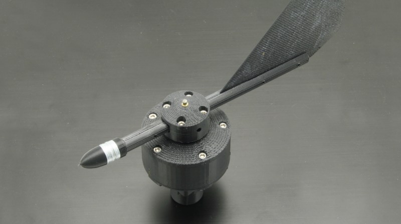
Have you ever wondered how an electronic wind vane translates a direction into a unique signal? It seems as though it might be very complicated, and indeed some of them are. [martinm] over at yoctopuce.com has an excellent writeup about measuring wind direction using just a single, easily printed disk and some phototransistors.
Commercial weather vanes often use complicated multi-tracked disks with magnets and reed switches, conductive traces and brushes, or some other means of getting a fine resolution. Unfortunately some of these are prone to wear or are otherwise more complicated than they need to be.
What makes [martinm]’s solution unique is that they have applied previous research on the subject to a simple and durable 3d printed wind vane that looks like it’ll be able to handle whatever global warming can throw at it. The encoder’s simplicity means that it could likely be used in a large number of applications where low resolution position sensing is more than enough- the definition of a great hack!
Adding more tracks or even more disks would enable higher resolution, but the 12 degree resolution seems quite good for the purpose. Such a neat wind vane design will surely be welcome if you want to 3d print your own weather station. Thanks to [Adrian] for the great tip!


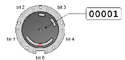
Yeah, Gray Code! (not grey code) And with an honorable pedigree too (see references).
It’s like quadrature coding, but with 5 instead of 2 bits.
But only 30 discernable positions (not 32), for reasons (see above noted pedigree).
So: trīgintāture coding!
Apparently you don’t get 00000 or 11111 — there’s always at least one 1 and at least one 0.
That’s odd. I’ve never heard that. All the Gray code sensors I’ve used had all zeros and all ones as valid positions. So 5 bits gave all 32 possible positions.
It’s because there isn’t separate tracks. All photo interrupters are gated by the same track.
There is a good article about STGC on: http://techref.massmind.org/techref/io/sensor/pos/enc/greycodes.htm apparently they encode for 2n-2 positions.
2^n-2
The Gray code is just one of many possible monostrophic codes. It’s easy to configure one to use all the available bit combinations: 0, 1, 3, 2, 6, 7, 5, 4, 0 for a 3-bit example.
I love it. I recently have a project that uses the Gray code, but I did not use a single track implementation. I may have to change my design…
https://hackaday.io/project/180815-3d-printed-rotary-time-tracker-for-task-management
“Single-track Gray Code”
From the Wikipedia article:
“Norman B. Spedding, however, registered a patent in 1994 with several examples showing that it was possible.[69] Although it is not possible to distinguish 2n positions with n sensors on a single track, it is possible to distinguish close to that many. Etzion and Paterson conjecture that when n is itself a power of 2, n sensors can distinguish at most 2n − 2n positions and that for prime n the limit is 2n − 2 positions.[75] The authors went on to generate a 504-position single track code of length 9 which they believe is optimal. Since this number is larger than 28 = 256, more than 8 sensors are required by any code, although a BRGC could distinguish 512 positions with 9 sensors.”
Nice design!
I made such wind vane a few years ago, but instead of using optical sensors, which are not very reliable once full of bugs (!), I used magnets and Hall effect FETs. The FETs handled 24V, so no outside electronics was required, only a few wires: 24V allows to have longs wires without problem.
I used a pseudo-Gray code (only I bit changed at a time, but not in a true Gray sequence). Magnets/sensors arrangement was computed by a Python script (kind of brute force!). With 4 sensors I had 16 positions. I don’t remember how many magnets I used, but the Python script was checking if the arrangement was symetrical, in order to keep the rotor balanced (even if it does not turn at 1000rpm).
I never really used it, as my 3D printed design was not great. Your project motivates me to reboot mine ;o)
I will make a web page of what I did so far…
Thanks for sharing!
How did you debug your system? Was it mostly software bugs or hardware bugs?
I think he mean wetware bugs
Agreed. How to keep the thing running long term without either water (or insect) induced damage is the real trick!
Reed Switches may be an alternative to Hall Effect FETS. They would probable need to be perpendicular to the magnet path. I can’t think of how you arranged the magnets. Perhaps on magnet and a cut up piece of a tin can can extend the range of magnetic influence.
Less problems with wetware bugs to lol.
This instructable based on STGC is also worth a visit: https://www.instructables.com/Absolute-Position-Encoder-With-Single-Track-Gray-C/ because of it’s cool encoder disc and the use of the encoder to drive a clock mechanism
So no wind at night? Wondering if you could use some contacts and ballbearings orso.
It’s optical, but it’s self lit with LEDs. Should work at night no problem.
Same idea with 9 bits (1 degree resolution):
https://www.thingiverse.com/thing:4590077
Could you add a 1:30 gear to a second shaft, put a 2nd 30-way encoder on that, and get 10 bits of measurement? I know, that’s a steep ratio to do in one step. Multi stage gears would suffer increased backlash and backlash undoubtedly would degrade resolution. Not to mention of the main shaft did even 30RPM, the secondary would spin North of 900, so balance issues there. Maybe just paint the pattern on the secondary shaft and use reflective sensors, to keep the moment of inertia and centrifugal forces down?
Also seems like you could go low-tec, and use a copper track, and replace the sensors with simple brush contacts .. although denouncing that would be probably be challenging.
Just throwing ideas into the wind, there, btw
It’s a wind sensor, so most of the issues mentioned shouldn’t really apply. I mean, if you’re applying it to a different type of sensor, maybe (wheel position?). You’re probably better off just making your encoder bigger than trying to step down and do two of the same 5 bit encoder. Same concept with 10 bits would get you something like 1020 positions, which is more than doing 2 5-bit encoders, and simplifies your life (don’t have to worry about balancing so much, everything moves much slower). You just need to end up making a bigger encoder wheel.
why bother with all that rigamarole?
If you don’t want to use optics, just use a rotary variable differential transformer: one chunk of iron, two coils, four wires, and easily better than 1 part per thousand resolution.
Well less wires but for that expense you could use a high precision IC based magnetic absolute position encoder.
Or 3D print the former and hand wire it.
Another possibility is a magnetic rotary encoder. I used to sell breakout boards for the austrian microsystems AS5045 and associated family of chips. You stick a magnet on the end of a shaft, and put this chip near the magnet, and it gives you 8 or 10 or 12 (depending on the chip) bits of resolution, so you can easily get sub-degree accuracy. It’ll output quadrature encoding if you’re into that or you can read it via an SPI-like interface, and there are a bunch of other options if you work harder. (And it’s fast: it’ll update readings faster than the SPI interface can transmit them.) No contact, no moving parts, nothing to get blocked by bugs or dusty, other than if your dust has a lot of iron oxide in it. There are also other magnetic rotary encoders out there. I just happen to know the AS50xx series best.
Having spent a month or two on magnetic encoder selection I can confirm the other ones aren’t worth knowing. The AS series is top of the line.
Other hall rotary sensors like the MLX90316KDC-BDG-100-RE work great. See my wind direction device https://www.instructables.com/Accurate-Wireless-Weather-Vane/
Not a bad looking chip, I’ve added it to my list.
I love your “hardware store” BOM.
My current version is all 3D printed of clear abs, but is not wireless. The new version adds a propeller and hall sensor for wind speed and has slip rings for RS422 data/ power . It retains the hall rotary sensor but uses 3D printed gears to rotate the direction sensor magnet 1:1 geared to the airplane like body.
The wind instrument from the Nexus Marine instrument system, originally by Silva and now by Garmin, has a propeller with a rotating sphere mounted on the prop shaft. The prop and wind vane head rotate on a vertical shaft to orient the prop into the wind. A half-black and half-white sine wave mapped on the sphere’s surface is observed by two quadrature IR transceivers mounted 90 degrees apart that provide simultaneous information about wind speed and wind direction in one instrument. The transceivers each output a 0/5V pulse train of variable frequency and duty cycle. The frequency of the pulse train is proportional to wind speed and atan2() of the two duty cycles determines the wind direction. Very simple and elegant. I provided some documentation for it here: https://hackaday.io/project/179262-logging-sailboat-instrument-data/details.
@Paul, I believe that, sadly, your comment was truncated before your explanation on how you extend the usual range of an RVDT to 360 degrees.
Rigamarole.
True! Well caught!
A typical RVDT is only ratiometric (measures a ratio of amplitude only), and so has a 180 degree ambiguity.
You need the phase-sensitive cousin, more commonly known as a resolver. Though it’s possible to run them on only 4 wires (common, drive, sin, cos), you’ll most often see them will all six wires brought out. (and, yes, that’s three coils: you do need a drive coil)
This was done in 2013, most have been hiding in that dusty corner where no one looks.
I want to build a bluetooth (lower power) weather unit with a wind speed for wind speed and a wind speed for charging the battery, a solar cell for sunlight intensity and a solar cell for charging the battery and a wind direction for wind direction – though if could also charge in a cyclone :)
Then I have no remote wires to worry about.
The only thing I worry about with the design here is that the shaft is held by a pressure fit to the wind vane. I worry that this will ware prematurely because the back of the wind vane is not symmetrical height-wize is is going to exert torque on the pressure fits.