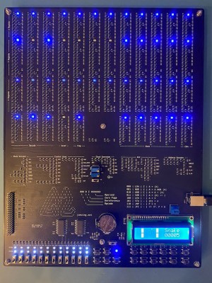
[Joe Wingbermuehle] has an interest in computers-of-old, and some past experience of building computers on perfboard from discrete transistors, so this next project, Q2, is a complete implementation of a PDP8-like microcomputer on a single PCB. Like the DEC PDP-8, this is a 12-bit machine, but instead of the diode-transistor logic of the DEC, the substantially smaller Q2 uses a simple NMOS approach. Also, the DEC has core memory, but the Q2 resorts to a pair of SRAM ICs, simply because who wants to make repetitive memory structures with discrete 2N7002 transistors anyway?
Like the PDP-8, this machine uses a bit-serial ALU, which allows the circuit to be much smaller than the more usual ALU structure, at the expense of needing a clock cycle per bit per operation, i.e. a single ALU operation will take 12 clock cycles. For this machine, the instruction cycle time is either 8 or 32 clocks anyway, and at a maximum speed of 80 kHz it’s not exactly fast (and significantly slower than a PDP-8) but it is very small. Small, and perfectly formed.
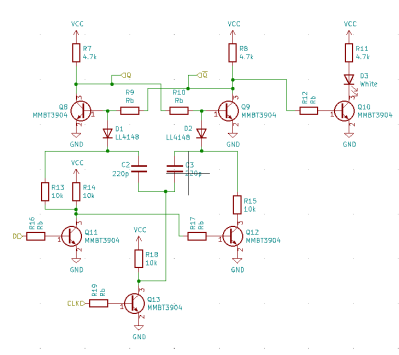
The machine is constructed from 1094 transistors, with logic in an NMOS configuration, using 10 K pullup resistors. This is not a fast way to build a circuit, but it is very compact. By looking at the logic fanout, [Joe] spotted areas with large fanouts, and reduced the pull-up resistors from 10 K to 1 K. This was done in order to keep the propagation delay within bounds for the cycle time without excessive power usage. Supply current was kept to below 500 mA, allowing the board to be powered from a USB connector. Smart!
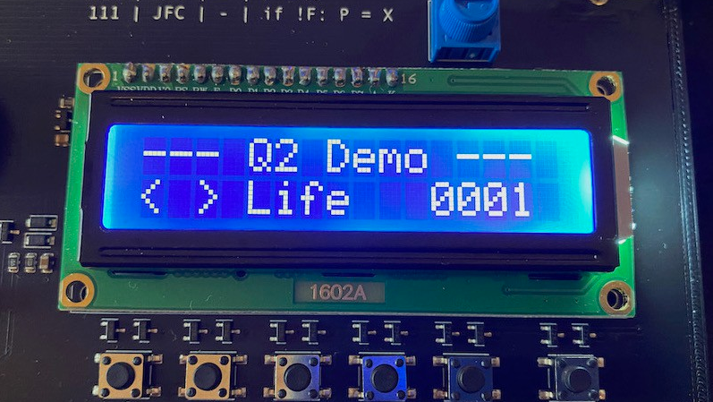
Memory is courtesy of two battery-backed 6264 SRAMs, with the four 12-bit general purpose registers built from discrete transistors. An LCD screen on board is a nice touch, augmenting the ‘front panel’ switches used for program entry and user input. A 40-pin header was added, for programming via a Raspberry Pi in case the front panel programming switches are proving a bit tedious and error prone.
In terms of the project write-up, there is plenty to see, with a Verilog model available, a custom programming language [Joe] calls Q2L, complete with a compiler and assembler (written in Rust!) even an online Q2 simulator! Lots of cool demos, like snake. Game of Life and even Pong, add some really lovely touches. Great stuff!
We’ve featured many similar projects over the years; here’s a nice one, a really small 4-bit one, and a really big one.


Awesome – amazing what you can do with 1000 discrete transistors and a couple of 8K RAMs!
I like this! :D
The PDP-8/S (which was released after the original PDP-8) uses a bit-serial ALU architecture; all other models, including the original “Straight-8,” use a traditional ALU.
The article confuses bit slice which combines 1 bit wide circuits into wider words
https://en.wikipedia.org/wiki/Bit_slicing and bit serial which iterates wide words one bit at a time using a single bit circuit https://en.wikipedia.org/wiki/Bit-serial_architecture
Yes, that’s a typo. Its a bit-serial ALU. Fixed.
Noyce !!!
Very nice and clean. I like it.
Very impressive! Certainly a labor of love.
But I wonder… It’s essentially RTL, so the pull-up resistors make it pretty slow. If you’re using NMOS MOSFETs, why not use PMOS MOSFETs as well and make it CMOS? It should take fewer parts, and be significantly faster and lower power at the same time.
Why so blue? Amber or red would be much more fitting for such a retro computer. Still, a very cool project.
“warm white” LEDs would look very much like incandescent lamps, which is what many minicomputers used before LEDs became ubiquitous. I think the PDP-8 was one of these.
The first computer I had access to as a kid was a HP2100A, and it definitely used incandescent bulbs behind its translucent bit keys.
The early PDP-8s used incandescent lights, yes.
Personally, I’d replace “would look very much like” with “vaguely resemble”.. I do still have real incadescent lamps and they are by far more warm-looking and eye friendly. Also, they have a smoother transition between on/off. LEDs don’t have that feature without additional circuitry. When I look at fast-blinking LEDs, I do feel a bit sick sometimes, but do not feel that way with incadescent lamps. Anyway, I’m no expert in epilepsy. And I don’t mean to badmouth LEDs all together, either. There are some interesting and cool looking schematics for LED faders. :)
When the singularity hits some of these types of machines will be the only ones that don’t get totally owned and assimilated. I would like to take this “from sublogic component up” type build all the way to a machine that can run a form of Linux with SSH client and server capabilities as a minimum with the encryption being also capable of single use XOR from physically shared data “pads”. Also portable, solar powered and using cognitive radio to form mesh links. Even if the thing is the size of a suitcase, or large camping backpack. Doable?
Lots and lots of people making computers out of either 74-series chips or 2N3904 BJTs or 2N7002 MOSFETs, but pretty much everybody is using SRAM chips for RAM and flash for ROM (notable exception for that guy who used mechanical switches for ROM). Question is, does anybody have a recipe for a ferrite that can be mixed and cooked in a home shop, that would have suitable characteristics (a sufficiently steep B-H curve with lots of hystereses) for making core memory? Or maybe ideas for a head-per-track drum or disk? (Let’s not even think about storage CRTs!) Maybe a big delay line memory? It seems like we’re leaving out that one thing that was the biggest challenge for minicomputers – inexpensive but (sorta) fast memory. They once called core memory “buck-a-bit” for a reason.
+1
I also often wonder why no diode matrixes are used in replicas.
In the amateur radio scene, almost no one seems to care about making new morse keyers by using plain diodes. It’s all microcontrollers now. The oldest that’s seemingly still being used are EEPROMs. And the programs for creating the bit patterns are all ancient and DOS based. The latter isn’t bad per se, since there are plenty of DOS emulators, but.. It seems there’s little interest in the hobby to recreate the more mechanical devices. Originally, morse keyers used rotating wheels and light barrieres or metal contacts, but almost no documentation can be found about these. And last, but not least, the morse keyer circuit of the famous OSCAR-1 satellite is still a mystery. Replicas use, you guessed it, microcontrollers to simulatione the original keyer.
Well, the guy I mentioned who used DIP switches for ROM, probably also had a diode for each switch, so it was kind of a HAROM (Hand-Alterable ROM). That was featured in a HaD article, BTW: https://hackaday.com/2020/10/23/relay-computer-consumes-six-years-and-4-5-suitcases/ This machine used 500 dip switches for program ROM, and another 384 for the microcode. But it was a relay computer. I haven’t seen any relay computers using solid-state memory. I guess that’s too big a stretch.
I used a diode matrix to encode the keyboard on my first computer, which was a Z-80 machine, which at the time (1979) was the easy way to do it. My boss then was a Ham, and I helped him wire a Morse keyboard that used diode encoding as well. And which WORKED! I mean, to me that was more impressive than making a computer using a Z-80 CPU, because his project DIDN’T use a CPU. It was all discrete logic.
But alas, it turns out (no surprise) that electronically reading and displaying Morse is harder than encoding and sending it. He was also working on a Morse reader, but I don’t think he got that working while I knew him. I guess that was the FT8 of its time, allowing low-power DX without having to learn Morse code.
There were commercial CW decoders, I have no idea how well they worked. But expensive, for the military or commercial point to point.
But Ham Radio magazine for November 1971 had a CW decoder, using transistors and logic. Sent the output to a strip printer. About 1974 thesame guy had his matching CW encoder in the magazine.
Oscar 1’s keyer was really simple, send 6 dits, with a space after four. So it was simpke, but also not likely to be useful for other characters. And it was bound to use germanium transistors, a bit harder to find at this point. As I recall, they got permission for using “hi” as the callsign, that’s not going to happen today.
Very few hobbyists made mechanical keyers. You’d need a metal shop. I do recall seeing a Morse keyboard that used an old typewriter for the keyboard.
If you want to build something retro, the old magazine articles are there. But why use diode matrixes once there were microcomputers, which made it simpler but also you could add features? It’s much easier reprogramming than rewiring a diode matrix to send canned messages.
On one hand, people seem isolated from the past, so nothing counts unless it’s on the internet. On the other, there’s nostalgia for things not experienced. Very few people built computers before microprocessors, but but they got something not all that inferior to commercial computers. But anything built from scratch now can give only mediocre results. And it all seems too much like living in the past, rather than looking forward.
I don’t think it’s “nostalgia for things not experienced”, although I can see where you would get that from. I mean, that’s my reaction to young people who are into vinyl records, which were a barely-tolerable experience when our only choices were that or cassette tapes, which were even less tolerable.
But I digress. No, I think this is more a matter of making things where you can identify exactly what each part does. Which doesn’t quite cover it either, because if you make something with a microcontroller, that’s one part that does does exactly .. everything. No, what it is about is being able to see each functional part. Even if you program the microcontroller in assembly language, it’s still this one atomic, opaque block of epoxy. If you can’t see moving parts, the next best thing is, i guess, blinking LEDs or maybe clicking relays or beeping beepers, but only if they have something to do with what’s going on in the circuit, and the NEXT best thing is lots of non-moving, non-blinking/clicking/beeping parts.
Do you know the reason for the germanium transistor requirement? I’ve not heard of this before.
Probably not so much a requirement as that the germanium transistors would have been cheaper, had better performance, and been more common than the silicon transistors of the day.
Oscar1 was built in 1961. Silicon bipolar junction transistors were invented in 1954, but still weren’t up to the performance of the germanium transistors.
https://en.wikipedia.org/wiki/History_of_the_transistor#Switch_to_silicon
You can buy tins of ferrite cores meant for core memory on eBay. They’re pretty cheap.
Where’s the fun in that? But thanks!
In the late seventies, there were some articles in “73” about using toroids in encoders. They were the same toroids as used for making coils. I thought it was akin to core memory, but not certain. Loop wire through the cores that represented that bit.
Yes, I’ve seen “magnetic logic”, but there’s a special case for “core” memory: the toroids have to be able to have 1/2 their magnetizing current put through them in either direction for indefinite periods without changing the state of the core. This is because core memory uses 2D, or X-Y addressing, where half the magnetizing current is sent through the X wire, and the other half through the Y wire, and the core must only switch when it has both driven simultaneously, so that none of the other cores in the same column nor in the same row as the addressed core are affected. The core materials used for RF inductors and transformers generally have very low hysteresis, because this just translates to loss, which is usually undesirable. So these won’t work in 2D-addressed core memory.
Most of the PDP-8 series was fully parallel. It was just the PDP-8/S that was bit-sliced.
or as someone corrected above, bit-serial.
Awesome! There’re a lot of discreet CPUs, like this one (PDP-8 “like”), as well as of real CPUs like discreet 6502s, etc etc. Is anyone aware of a discreet version of the Z80?
A Z-80 is like an 8080 with a whole bunch more transistors thrown at it, and I haven’t even seen a discrete 8080. I’m thinking the thought process goes something like this:
self1: that would be really cool – a discrete Z-80.
self2: yeah, and you could start by building a discrete 8080, then upgrade it.
self1: I’d probably stop when I had a working 8080. I hate the 8080. Never mind.
And there’s another reason, I suppose.
The Z80 was made by the fathers of the i8080 who had left Intel.
So it makes sense that people had sympathy with the Z80. It was, at the time, made by a fine little company. And it was more advanced, too.
It worked with a single voltage (5v, TTL compliant).
Intel thus had to release its Z80 wannabe, the i8085, which never really catched on.
Later on, there were other reasons, too, as to why the Z80 kept being popular (aside from its price).
The popular Borland Turbo Pascal used Z80-specific instructions, I remember.
That’s one of the reasons, I suppose, CP/M emulators with a full Z80 core did catch on, but those which relied entirely on the quicker 8080 emulation mode of the NEC V20/V30 did not.
That being said, the 8080 assembler mnemonics were still used by Z80 users, on the other hand..
And CP/M-80 did keep running on pure i8080 CPUs or i8085s, too.
The 8085 was just an 8080 with simpler power supply needs, and a built in clock I think. It added a pin for input and a pin for output, and a few instructions for those pins.
It saw use, the CMOS version in the Radio Shack Model 100, and certainly in dual boards for the S-100 bus.
The Z80 saw a lot of use because of the built in DRAM controller, right as DRAM became a big thing. The extra registers and more complicated instruction set got press, but then worry about incompatability.
It’s a big stretch to call what the Z-80 had a “DRAM controller”. All it was was some extra circuitry that stole bus cycles from the CPU to send out memory addresses that exercised all of the rows or columns (sorry, don’t remember which) so that the DRAM chips would refresh themselves. You still had to multiplex the DRAM address lines externally, since all of the DRAMs being used at the time used shared address lines and separate row address and column address strobes. Which you also had to generate externally, because the Z-80 didn’t do that, either. Which is why even 64kB Z-80 systems often used static RAM, even though it was more expensive than DRAM.
I think that a bigger reason for the Z-80s success was that you could write code in about 25% less memory than on the 8080, due to the additional index registers and additional instructions. And also, fewer clock cycles per instruction, so code executed significantly faster as well. It was basically everything the Intel engineers had wanted to put in the 8080.
I do not know of a discrete version yet, but the Z80 had been recreated using modern technology.
https://original.sharpmz.org/z80glass.htm
I’ve always wanted to build something like this. I’ve come as close as to hit the checkout button on Digikey a couple of times. Then I remember that I have adhd and I just don’t have the patience to go through with it.
Cool project, but…
I assume the 2N7002 was chosen for economic rather than performance reasons. A 50 pf input capacitance means a lot of current is needed to achieve high speeds.
Which brings up another thing: old-school CMOS WAS pretty slow. What allowed CMOS to replace both NMOS and TTL, as the invention of the self-aligning gate for MOSFETs, which allowed gates to be dramatically reduced in size, lowering the capacitance. Not just flexing here, though: what this means is that you’ll never see a discrete MOSFET computer that has a decent clock rate and low power consumption, because cheap MOSFETs don’t use tiny self-aligned gates.