Millimeter-wave Radars used in modern cars for cruise control and collision avoidance are usually designed to work at ranges on the order of 100 meters or so. With some engineering nous, however, experimenters have gotten these devices sending signals over ranges of up to 60 km in some tests. [Machining and Microwaves] decided to see if he could push the boat out even further, and set out machining some waveguide combiner cavities so he could use the radar chips with some very high-performance antennas.
The end goal of the project is to produce a 53 dBi antenna for the 122GHz signal put out by the mmWave radar chips commonly found in automotive applications. Working at this frequency requires getting tolerances just so in order to create an antenna that performs well.
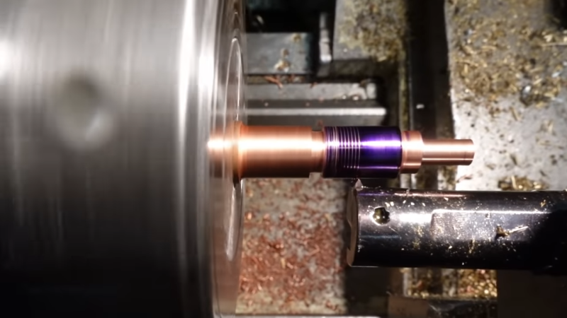
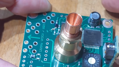
Plenty of fine lathe work and cheerful machining banter later, and the precision waveguide is done. It may not look like much to the untrained eye, but much careful design and machining went on to make it both easy to attach to the radar and parabolic antenna system, and to make it perform at a high enough level to hopefully break records set by other enterprising radio experimenters. If that wasn’t all hard enough, though, the final job involved making 24 of these things!
There aren’t a whole lot of microwave antenna-specific machining channels on YouTube, so if you’ve been thirsty for that kind of content, this video is very much for you. If you’re more interested in antennas for lower frequencies, though, you might find some of our other stories to your liking. Video after the break.
[Thanks to MendesL for the tip!]


Heh, apparently gaming YouTube algorithms has gotten so far that this channel is sticking AI-generated female face in the corner of the screenshot.
talk about burying the lede! that’s a hack in itself!
At 122GHz (2.46mm wavelength) a parabolic antenna with a 65% aperture efficiency and 53dBi gain will need to have a 43cm (17 inch) physical diameter.[1] Not very big; pretty easy to aim on a tripod with a rifle or spotting scope and a bit of knowledge about how millimeter wavelength signals propagate in Earth’s atmosphere.[2][3]
* References:
1. Parabolic Antenna – Gain
https://en.wikipedia.org/wiki/Parabolic_antenna#Gain
2. 122GHz News – Links to videos of 122GHz point-to-point operating.
https://ghz-europe.com/122ghz-news/
3. WB2BYP at 4.9 km on 122 GHz
https://www.youtube.com/watch?v=us90S6IJg_o
https://www.youtube.com/watch?v=us90S6IJg_o
Hm…it is hard for me to understand any jokes, because I am not native english,
but what is so special about it? I think everyone who can machine to a resolution of 0.001mm
can do this. (no center drill used???)
I thought the magic is in the access to a simulation program and do the simulation
for the antenna. How is this done here?
And is it a good idea to use MS58 for the job? I would expect that will turn to dark brass after
some time, I guess that the wave will than flow different and the same will happen if you use
any kind of coating on the surface, isn’t?
Ups..made a mistake. I mean 0.01mm. :-)
122GHz?
Oi, do you need a loicense for that band?
How many people in a distance of 100m around your house can measure it? :-)
I am not sure if the gouverment can measure it now. 120 and 240Ghz is now still
the stuff that happens most of the times inside an university.
And I think we can trust that most people can not do this at home. Almost everything
is expensive in this frequency range. It is easy to put out 1000Euro for a roger-pcb for it.
Which is why I sometimes worry about using anything apart from the ISM band, since I live really close to an airport. Read somewhere routers on 5GHz scan for weather radar being present, before allocating a frequency slot. Think this is it:
https://en.wikipedia.org/wiki/Dynamic_frequency_selection
Thanks for clarifying it is probably safe to use. My question was stemming from the worry that someone else might use it already, least I want is someone knocking on my door. Hence the loicense joke :)
in many parts of EU, the allowed channels are fixed, with a chunk of the 5GHz missing – this is what’s reserved for weather radar.
“used in modern cars for cruise control and collision avoidance … gotten these devices sending signals over ranges of up to 60 km”
What could possibly go wrong?
given that other cars equipped with the same sensor may be much closer than that and have to be able to deal with the interference – nothing.
The beamwidth would be ~0.17 degrees (1m) to ~0.11 degrees (1.5m). So unless the cars were driving through the middle of the beam they are not going to see any signal.
The Beamwidth in degrees for a “typical” Parabolic Antenna is 70 * wavelength (in meters) / diameter of the parabolic reflector (in meters)
The “silicon radar” chip (At a guess a TRX_120_001) is tuned to 122.388 GHz which has a wavelength of 0.0024495 meters.
And the diameter of the satellite dish looks to be about 1 meter maybe 1.5 meters.
I didn’t watch the video so pardon my question: How much power do these things output or asked the other way round, what would happen if somebody or something alive would walk/fly/… in front of this antenna? I guess it’s not a lot of power so it’s not dangerous, am i wrong?
I suppose, you mix the frequency and amplitude here.
https://courses.lumenlearning.com/physics/chapter/24-4-energy-in-electromagnetic-waves/
If it is a TRX_120_001, the datasheet says:
Low power consumption of 380mW
Supply voltage (3.3 V, 112mA typ.)
Supply current consumption ICC
typical: 112
max: 125 mA
Supply voltage VCC
max: 3.6 V
Transmitter output power PTX
min: -7 dBm (0.20 mW)
typical: -3 dBm (0.50 mW)
max 1 dBm (1.26 mW)
So not much RF power at all. About the same power as a Bluetooth earpiece that people stick into their head (Bluetooth Class 3 radio 0dBm)
Ok, ~1mW is not something to worry about. Thank you.
If a car’s radar can’t disambiguate its own echos from the signals of every other car-borne radar in the vicinity, it’s got serious problems.
I doubt very much this tight beam not even aligned with a road is going to even be noticed, let alone pose any interference issue.
*chirp* *chirp* *chirp*
wouldn;t this be better done as a 3Dp
printer project ?
If you need radar for collision avoidance at 60km- in a car, you’re going too fast.. ;)
I’d be extremely interested in hearing your feedback on controlling burring and concentricity of the assembly in more complex structures. Please contact me.