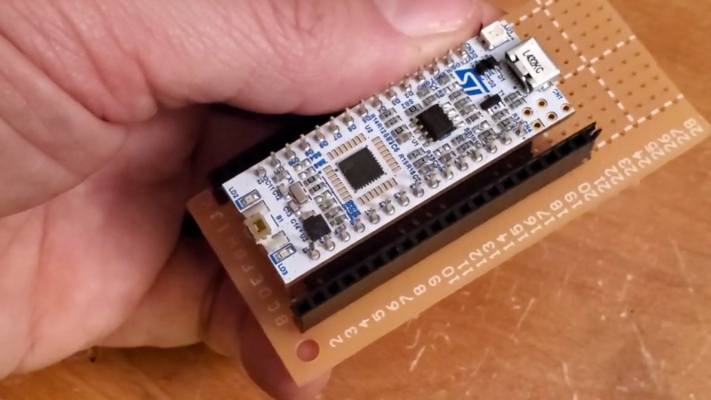
When you’re building a quick prototype or a one-off project it’s nice to be able to securely mount the various modules and development boards. Sometimes these boards have mounting holes, but often they don’t. As an example from the latter category, digital music instrument maker and performer [DIYDSP] shows us how to build a simple socket to mount an STM32 Nucleo-32 module.
The socket is built on a standard pad-per-hole piece of vector board cut to the desired size. Pairs of female pin header strips are soldered down to the board. The inner pair of headers is for the module, the outer pair is for your interconnections. The headers are connected up with short solder bridges, and [DIYDSP] recommends you extend the outer pair several pins longer than necessary. These extras can be used for additional power or ground points, or on some boards they could connect to the debug header pins. He prefers to use female sockets because that lessens the odds that an accidentally bent pin will short something out.
Final step is to drill your mounting holes in the desired location, and no more development boards free-floating and held up only by wires. Do you have any tips for mounting these kinds of modules, either individually as shown here or onto PCBs? Let us know in the comments.


What, perfboard is a hack now?
Sshhh. This is only one breakthrough away from inventing breadboard
I completely omit the pinheaders and solder the board to the perfboard only with the pads used and some corner pads for stability. This saves on height. The perfboard lives in a plastic case like those from hammond and I only use pinheaders for external connections were i mark one edge pin with typex to show pin one. I never use the same count of pins for the external pin headers more than once so it is obvious which connector goes where. Most of the time an extra power converter board and other small boards like stepper drivers are living on the perfboard as well.
@none: not every person reading this site has the same knowledge you have. Remember that. For most this info is in the 101, but dont forget the ones just starting. There are already too few people interested in electronics as it is.
This guy’s gets it
The risk of a stray male wire shorting to something (they are springy and will drag across a board, touching everything in the process) far exceeds the risk of bent pins, which will usually not touch the next pin because they spring back a bit, and you have to be extremely clumsy to bent pins like that without dropping the board.
What I usually do is remove the single pin housing from the dupont wire and insert them into a long single-row housing in the right place, that way you only have 2 connectors on such a board and they are much more secure.
You can still use the bottom side of the pins to mechanically mount the board, and maybe solder the power supply to that board, but leave it unconnected otherwise. For analog inputs, it does provide a place for a capacitor to ground.
Hu? He did show nothing here… Just added a board that converts the male to female pins, did accomplish nothing in cleaning up the messy wires or improving the connections.
He should have shown how to add all the small ‘sensor’ boards on that same base plate and used wirewrapp or similar to connect the stuff together.
Also, that was more troweling cement than soldering electronics.
lol
Here is something the same with wire wrap –
https://cdn.hackaday.io/images/6495531461474430682.jpg
https://hackaday.io/project/5565/gallery#786e0069ec06751206e7cc4c2cb29cf6
I’ve built a FIDO2 key with a STM32L432 using solokeys opensource solo1 firmware. They are legitimately nice MCUs, at a higher but still fair price. Debugger included on the board. My biggest problem still is finding meaningful projects. I’ve automated most tasks in my life where the time save vs time invested benefit was good.
*FLOSS actually
Topper tip: an Arduino Nano fits in a 32-pin DIL IC socket. Always align D1/TX to pin 1, and you can ensure that you can just swap it in and out between projects easily. Plus because the nano pins are larger than usual IC legs, it makes a very solid connection.
Just buy a $4 Arduino Nano screw terminal adapter. If the width between the two sides isn’t right just cut it in half then glue them to something.
My 2c worth on the header “vs” sockets.
The sockets used in this video have the flat “Y” shaped contacts that are very very poor quality and have very small contact surface area and are prone to disconnecting.
There are better quality ones. Most of the duel row IDC connectors use the better quality and it’s the same storey for surface mount headers/sockets.
The image below helps explains.
https://cdn.hackaday.io/images/2365381490081684686.jpg
Tune in next week for how to push an Arduino nano into a breadboard
I prefer the PCB’s which come with loose connectors.
I use the square pin headers for “other stuff” and solder in the male connectors with thinner round pins.
These fit directly into the “high quality” “turned” DIP sockets (or similar single row headers. It’s more reliable and overall smaller formfactor.
There’s a trick to buying those “thinner round pins” and that’s knowing the diameter. I had a lot of trouble finding them. They were something like 0.0318″ or something just as obtuse.
Pro Tip! Breadboard patterned protoboard such as adafruit Perma-Proto, etc does this way easier, without the need for risky solder bridges, and provides multiple solder points per each pin. https://www.adafruit.com/product/571
Just google “breadboard pattern protoboard”